Download
1 / 40
400 likes | 537 Views
This document outlines the requirements and upgrade plans for the CMS experiment in light of the SLHC. It details the motivation for the upgrade, assesses subsystem performance needs, and discusses the challenges associated with trigger efficiency and tracking systems. Key areas of focus include maintaining performance for physics requirements, optimizing trigger rates, addressing material budget concerns, and enhancing tracking capabilities. The plans aim to ensure that the CMS detector continues to perform effectively in the next phase of high-energy physics research.

E N D
CMS Upgrade Requirements and Upgrade Plans Hans-Christian Kästli, PSI 11.6.2008 CHIPP Workshop on Detector R&D
Contents • Introduction & Motivation • Part I: Subsystems • Trigger • Tracker • Calorimeters & Muon system • Common Projects • Part II: Phase I barrel pixel upgrade Contains material from J. Nash, G. Hall, R. Horisberger CMS upgrade plans 11.6.2008 1/32
A realistic (?) upgrade scenario [J. Nash] CMS upgrade plans 11.6.2008 2/32
Requirements from Physics • Performance @SLHC need to be at least as good as now • Especially true for forward jet tagging and b-tagging • pT resolution ok as is • IP resolution ok, but need to be kept at this level at SLHC (radiation damage reduces tracker resolution) CMS upgrade plans 11.6.2008 3/32
Organisation CMS upgrade plans 11.6.2008 4/32
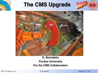
The CMS Experiment CMS upgrade plans 11.6.2008 5/32
Triggers • Level 1 trigger consists mainly of: • Muon triggers from individual stations (local) • Calorimeter triggers • e/g: isolated ECAL trigger towers, no HCAL energy • t: isolated ECAL + HCAL trigger tower • jets: ECAL + HCAL energy in cone • Higher level trigger: • Combine local muon to global muons • Combine muon tracks with tracks from inner tracker to improve pT resolution • Correlate calorimeter trigger with tracker information (e/g+t/QCD discrimination ) • At SLHC most of these triggers at level 1 will exceed any realistic trigger rate. • There is a severe trigger problem for CMS at L=1035cm-2s-1 ! CMS upgrade plans 11.6.2008 7/32
Level 1 Trigger at SLHC Level 1 trigger has no discrimination for pT>~20GeV/c (MHz) • and jet rates • Problem: isolation of calorimeter towers • Same problem for electron trigge Muon trigger rates Problem: insufficient pT resolution from muon system CMS upgrade plans 11.6.2008 8/32
Level 1 Trigger at SLHC • Guided from high level trigger at LHC: • Muon system needs tracking information on level 1 • Need trigger layers/trigger information from tracker • pT measurement-> outer radius • Need correlation between muon and tracker • Electron trigger needs tracking information on level 1 • Z-vertex information for cluster-track matching • g rejection -> innermost tracking layers (conversion) • Need correlation between calos and tracker • t trigger needs tracking information on level 1 • Jet rejection -> complete tracking • Need correlation between calos and tracker • Tracking triggers absolutely needed • But: cannot do everything. Need priorities and/or compromises • Very challenging, only vage ideas around CMS upgrade plans 11.6.2008 9/32
track reconstruction of hadrons in b-jets BUT: it is heavy! This shows up in the photon conversion rate, in the track reconstruction efficiency for pions and in the track fake rate Will become a problem in SLHC Tracking @ LHC pT and transvers impact parameter resolution • CMS has an all-Si tracker with • 3 pixel barrel layers • 10 strip barrel layers (4 stereo) • 2 pixel endcap disks • 3+9 strip enddisks (2+2 stereo) • The expected performance is excellent as indicated on the right CMS upgrade plans 11.6.2008 11/32
Material Budget • In very central region ~0.3 radiation length • A lot of materials from cables in forward • region! • In future difficult to bring the power in • Support structure contributes a lot, but • cannot gain much in inner part • Except: fewer layers • less material, less power, less costs • Why are there so many? • Serious concern about pattern recogni-tion with so few points (unprecedented design and environment) • Probably can be relaxed (although still no full simulation of loopers… and we haven’t seen data yet!!) CMS upgrade plans 11.6.2008 12/32
Going to SLHC 25 ns bunch structure CMS upgrade plans 11.6.2008 13/32
algorithmic efficiency • fake rate Tracking with 500 min bias events Inner layers of strips reach 30% occupancy on every xing! • Study of current CMS tracker for Heavy Ion events • Track density very similar to 50ns running • dnch/dh/crossing ≈ 3000 • Tracker occupancy very high • Need more pixel layers/shorter strips • Tracking is possible (thanks to pixel!) • When tracks are found they are well measured • Efficiency and fake rate suffer • CPU Intensive Pixel layers Momentum Resolution Impact Parameter Resolution CMS upgrade plans 11.6.2008 14/32
Key Areas for Tracker R&D • Reducing and delivering power at lower voltage… • DC-DC conversion, serial powering • …and removing it, with limited material • CO2 cooling, other cooling schemes • Ensuring sufficiently rad hard sensors are available • and establishing the manufacturing capability with industry • A new readout & control system using modern technologies • radiation hardness may be a minor point this time • Developing components to build one or more layers which can contribute to the L1 trigger • these layers must also be light and power-efficient • Designing a tracker layout from these which will meet the physics objectives (last, but by no means least…) CMS upgrade plans 11.6.2008 15/32
Tracker related R&D Projects CMS upgrade plans 11.6.2008 16/32
Working Group Organisation • These goals motivated the R&D structure • active for 12-18 months CMS upgrade plans 11.6.2008 17/32
Barrel Strawman Designs • Strawman A Geometry: • Perturbation of current tracking system • 4 Inner pixel layers, 2 strixel + 2 short strip layers (TIB), 2-strixel + 4 short strip layers (TOB) • Strawman B Geometry: • Design radically different from current tracker • Super-layers, each with two doublet layers (integrated tracking/ triggering layers); 3 inner Pixel layers Short strips Superlayer Pixel layers Strixel layers, could be doublets Mini-strip or Pixel doublets CMS upgrade plans 11.6.2008 18/32
Strawman B: triggering + local data reduction • High pT tracks point towards the origin, low pT tracks point away from the origin • Use a pair of sensor planes, at ~ mm distance • Pairs of hits provide vector, that measure angle of track with respect to the origin • Keep only vectors corresponding to high pT tracks • Stacks of 2 sensor pairs, at ~ cm distance • Redundancy • Track stub provides higher resolution local pT measurement • Two level data reduction But: Material budget? How light can we build this? Power? Triggering needed, but mustn’t geopardize tracking α CMS upgrade plans 11.6.2008 19/32
Hadron Calorimeter • Forward calo may be blocked by potential changes to the interaction region. This has a direct impact mainly in the case of looking for WW scattering • Upgrade proposal for new trigger/DAQ readout • New SiPM with higher gain/less noise • Allows to • add timing information • make longitudinal segmentation to reduce sensitivity to min bias • Both Calorimeters suffer degraded resolution at SLHC • affects electron ID, Jet resolutions CMS upgrade plans 11.6.2008 21/32
Electromagnetic Calorimeter • ECAL • Crystal calorimeter electronics designed to operate in SLHC conditions • VPT in Endcap and Endcap crystals themselves may darken at SLHC • Very difficult to replace • At SLHC, per Trigger Tower, per crossing, 12 expected ( rate in ECAL ~2.4 MHz/cm2), <PT> ~3 GeV No empty ECAL towers • The readout of every crystal is technically possible, by increasing the readout rate from 0.8 Gbits/s to 14 Gbits/s for 25 crystals. • full calorimeter information could be used in the level 1 trigger decision • Proposal byR. Rusack, Proposal for ECAL R&D (Phase II), DPG 27-FEB-08 • Physics benefits arguable but definitely not proven • Major effort to remove the supermodules, remove the LV cables and replace the front-end boards, check and re-install. • Requires un-cabling of the tracker to remove the ECAL supermodules • Radiation levels for all this work CMS upgrade plans 11.6.2008 22/32
Muon System • System front end electronics look fairly robust at SLHC • Cathode Strip Chambers/RPC Forward • Drift Tubes /RPC Barrel • Trigger electronics for the muon systems would most likely need to be replaced/updated • Some Electronics is “less” radiation hard (FPGA) • Coping with higher rate/different bunch crossing frequency • May have to limit coverage in ( > 2) due to radiation splash • This effect will be known better after first data taking, potential additional cost of chamber replacement CMS upgrade plans 11.6.2008 23/32
Infrastructure Modifications: Yoke • Supplement YE4 wall with borated polythene • Improve shielding of HF PMT’s • possibility of increased YE1-YE2 separation to insert another detector layer? CMS upgrade plans 11.6.2008 24/32
Common Projects There are many common R&D topics which must be pursued by ATLAS and CMS A Joint meeting was held last year to discuss possible joint R&D • ACES meeting - http://aces.web.cern.ch/aces/ • Will repeat later this year Topics include • Link Technology • Versatile link project (CERN): rad hard physical network layer for optical links • GBTproject (CERN): gigabit optical link for data/control/trigger • ASIC technology • 130nm technology • Power distribution • Funding from EU • Rad hard DC-DC converter (CERN) • Small contribution from PSI: on-chip DC-DC conversion • Cooling • Tests on CO2 cooling hosted by CERN cryolab • Radiation/shielding issues CMS upgrade plans 11.6.2008 26/32
Phase 1 Tracker Upgrade • In 2013 need to replace > 50% of pixel barrel modules & probably optical-links due to radiation damage. Pixel module fluence limit = 6x1014 cm-2 (TDR) • Barrel mechanics constructed for quick insertion/deinstallation • Radiation damage & activation probably require a complete rebuild of barrel pixel • Services (cables, fibres and cooling tubes) will have to be re-used. No replacements, no additions. • Rest of tracker will be unchanged (long shutdown would be needed to access strip tracker) • PSI/UNIZ/(ETHZ) are interested in building a new barrel pixel detector for the phase I upgrade • Several possible scenarios presented by Roland Horisberger: • http://indico.cern.ch/conferenceDisplay.py?confId=28746 • No official proposal yet. CMS upgrade plans 11.6.2008 28/32
Options for Barrel Pixel Readout analog 40MHz analog 40MHz analog 40MHz analog 40MHz m-tw-pairs digital 320MHz m-tw-pairs digital 640 MHz m-tw-pairs Power as now as now as now as now as now DC-DC new PS Cooling C6F14 C6F14 CO2 CO2 CO2 CO2 Comment as 2008 Data loss reduction Large gain in material budget Simplifies module design Test structures designed Uunlikely for 2013 (services) Pixel ROC PSI46 as now 2x buffers 2x buffers 2x buffers 2xbuffer, ADC 160MHz serial 2xbuffer, ADC 160MHz serial Option 0 1 2 3 4 5 Layer/Radii 4, 7, 11cm 4, 7, 11cm 4, 7, 11cm 4, 7, 11cm 4, 7, 11cm 4, 7, 11, 16cm CMS upgrade plans 11.6.2008 29/32
Option 0: Simple Replacement • Pro: • Data taking and physics output of CMS experiment is not disturbed • Pixel detector is well calibrated, aligned, efficiencies are studied, algorithms are stable • No big brainpower has to be drafted for rebuild focus on physics output of CMS • Time schedule and costs are likely under control • Con: • Rebuild detector conceived in 1997 • Detector designed for Luminosity of 1x1034 and will develop substantial inefficiency for 4cm layer at 2x1034 • We did a reasonable job in material budget (1.92%/Layer at h=0) but could be improved, especially in eta region 1.4-2.3 • Present pixel needs considerable algorithmic know how to deal with gain variability of optical chain and event decoding CMS upgrade plans 11.6.2008 30/32
Option 2: CO2 cooling • Use bi-phase CO2 cooling and benefit from reduced material budget ! • allows long cooling loops (~2-3m) with very small diameter pipes (~1mm) for thermal loads of ~100 W • Present C6F14 monophase has parallel cooling pipes with manifold and large diameter silicon hoses for feed and drain in front of FPIX tracking region. • New CO2 allows serialized pipes without pressure drop problems and therefore reduces resident cooling liquid by large factor. • Density of liquid CO2 is ~ 1.03 g/cm3 compared to 1.76 g/cm3 of C6F14 • Needs considerable engineering support from CERN for CO2 cooling plant. Material distribution budget for 3 barrel layers C6F14cooling CO2cooling CMS upgrade plans 11.6.2008 31/32
Option 2: Weight of one half barrel BPIX nowBPIX CO2 cooling Empty mechanics : 1103 g 550 g ~94g , 1.5mm pipes 384 Module 2.27 g each 872 g same 384 Signal cable (21.7mg/cm) 167g same 384 Power cable (10.6 mg/cm) 82g same 384 Power plug (42 mg/plug) 16g same 32 Print (15.61g each) with red power cable 499g same Cooling (C6F14) in tubes, manifolds & pipes 810 g 83 g 1.45mm pipes 2x1024mm Silicon tube + C6F14 in side 372g 5 g serial piping Total 3921g 2274 g Average material budget gain 1.72 , but in regionh=1.4 – 2.3 much more CMS upgrade plans 11.6.2008 32/32
Option 3: Replacing Kapton signal cables • use m-twisted pairs 2x125mm of enameled Copper CladdedAluminum (CCA) wires could provide a viable signal cable alternative for Kapton cables • Why? • Kapton cable can only bend in one plane. • O(1000) modules result in very complex, expensive, laboursome endflange prints, which contribute considerable in material budget in h range ~1.6 • Kapton cable length limited to < 40cm & expensive • Each 300mm plug is small & light, but ~800 soldered onto PCB with 21 traces in the sensitive tracking region are definitely not light ! • Benefit? • modules with long pigtail cables (~1.2m) allow transmission of analog output signals without impedance breaks. • More freedom in bending cables in all directions • Omit endflange print no soldering, simpler mechanics endflange, no PCB, no strong mechanics supports of PCB for plugging forces • Can move optical links with auxiliary chips further out (~50cm) to highh- range and remove material budget from sensitive tracking region CMS upgrade plans 11.6.2008 33/32
Option 3: Weight of one half barrel BPIX nowBPIX CO2 cooling Empty mechanics : 1103 g 550 g ~94g , 1.5mm pipes 384 Module 2.27 g each 872 g same 384 Signal cable (21.7mg/cm) 167g 14g 4x(2x125m) CCA 384 Power cable (10.6 mg/cm) 82g 68g 5x250mCCA 384 Power plug (42 mg/plug) 16g 0g 32 Print (15.61g each) with red power cable 499g 32gradial cables Cooling (C6F14) in tubes, manifolds & pipes 810 g 83 g 1.45mm pipes 2x1024mm Silicon tube + C6F14 in side 372g 5 g serial piping Total 3921g 1624 g gain 2.4x Large material budget gain forh=1.4 – 2.3 forward impact parameter CMS upgrade plans 11.6.2008 34/32
Summary and Conclusions • Luminosity will increase gradually • Due to radiation damage pixel needs to be replaced in 2013 anyway • Aim for pixel re-design in Phase I • Several options sketched • with large gain in material budget • possible within reasonable time scale/costs • Phase II upgrade: • Calo + muon system: minor upgrades needed • Trigger: need tracking information on level 1 • Tracker: completely new tracker needed to cope with high data rates. Extremely challenging project: • Increasing channel number • Must reduce power • Must provide trigger information • Should reduce material budget • Have to reuse present services • Time is short. Schedule has to be harmonized with ATLAS ! CMS upgrade plans 11.6.2008 35/32
Input to LoI preparation Examination will show this is an aggressive schedule When is t = 0? Constraints on LoI & TDR submission dates come from several places.. Input to TDR preparation NB “Remaining R&D” shows time left after “known” within R&D phase Geoff Hall 37 SLHC UG WG June 2007 May 2008 G Hall 37
Timescales Possible LoI 2010 & Phase I TDR? • Plan still seems a reasonable estimate, given 1 year shift • Examples of a few predecessor activities • Prototyping of readout ASICs, including any needed for triggering • Development of sFEC, control system & sFED • Prototype sensors with major manufacturers • Provisional mechanical support design • Development and evaluation of prototype modules • Definition of cooling scheme • Definition and proof of power distribution scheme • Development of cost model, TDR cost estimate • including establishing funding, preliminary negotiations with vendors • ~ 6 months for TDR preparations and writing • Submission of Phase II TDR ~ end 2012 • With approval and launch of approved construction project ~mid-2013 May 2008 G Hall 38
BPIX Optionsfor 2013 replacement/upgrade Option 0 1 2 3 4 5 Weight 3921 g 3921 g 2274 g 1624 g 1267 g ~ 2400 g estimate <X0 gain> 1 1 1.7 2.4 3.1 ~1.6 Start Date Aug 10 Nov 09 Nov 09 Nov 09 Dec 08 not possible for 2013 Costs 4.5 MCHF 5.0 MCHF 5.4 MCHF 5.4 MCHF 5.9 MCHF ~9.8 MCHF +0.4 MCHF Comments ROC wafers exist new ROC wafers 0.4 MCHF for CO2 plant - - - new ROC & TBM & HDI mod. pxFED & pxFEC DC-DC converters new LV Power Supplies