ADC TYPES
ADC TYPES. EE174 – SJSU Tan Nguyen. Types of ADC Flash ADC Successive approximation converter Counter Ramp Converter Integrating ADC. Flash ADC Also known as Parallel ADC A n-bit flash ADC uses 2 n-1 comparators and a encoder logic. Advantage: the fastest type of ADC.

ADC TYPES
E N D
Presentation Transcript
ADC TYPES EE174 – SJSU Tan Nguyen
Types of ADC • Flash ADC • Successive approximation converter • Counter Ramp Converter • Integrating ADC
Flash ADC • Also known as Parallel ADC • A n-bit flash ADC uses 2n-1 comparators and a encoder logic. • Advantage: the fastest type of ADC. • Disadvantages: limited resolution, expensive, large power consumption and low accuracy. • Applications: Data acquisition, satellite communication, radar processing, sampling oscilloscope and high density disk drives.
Flash ADC 3-bit flash ADC
Successive-approximation ADC Start Conversion (SC) A DAC is used to generate approximations of the input voltage. A comparator is used to compare Vin and Vappr. In each cycle, SAR finds one output bit using comparator. To start conversion, set SC = 1. When conversion ends, EOC = 1. Quite fast, expensive, high accuracy and one of the most widely used design for ADCs.
SuccessiveApproximation ADC Example • Goal: Find digital value Vin • 8-bit ADC • Vin = 7.65 • Vfull scale = 10
Successive Approximation ADC Example • Vfull scale = 10, Vin = 7.65 • MSB LSB • Average high/low limits • Compare to Vin • Vin > Average MSB = 1 • Vin < Average MSB = 0 • Bit 7 • (Vfull scale +0)/2 = 5 • 7.65 > 5 Bit 7 = 1
Successive Approximation ADC Example • Vfull scale = 10, Vin = 7.65 • MSB LSB • Average high/low limits • Compare to Vin • Vin > Average MSB = 1 • Vin < Average MSB = 0 • Bit 6 • (Vfull scale +5)/2 = 7.5 • 7.65 > 7.5 Bit 6 = 1
Successive Approximation ADC Example • Vfull scale = 10, Vin = 7.65 • MSB LSB • Average high/low limits • Compare to Vin • Vin > Average MSB = 1 • Vin < Average MSB = 0 • Bit 5 • (Vfull scale +7.5)/2 = 8.75 • 7.65 < 8.75 Bit 5 = 0
Successive Approximation ADC Example • Vin = 7.65 • MSB LSB • Average high/low limits • Compare to Vin • Vin > Average MSB = 1 • Vin < Average MSB = 0 • Bit 4 • (8.75+7.5)/2 8.125 • 7.65 < 8.125 Bit 4 = 0
Successive Approximation ADC Example • Vin = 7.65 • MSB LSB • Average high/low limits • Compare to Vin • Vin > Average MSB = 1 • Vin < Average MSB = 0 • Bit 3 • (8.125+7.5)/2 = 7.8125 • 7.65 < 7.8125 Bit 3 = 0
Successive Approximation ADC Example • Vin = 7.65 • MSB LSB • Average high/low limits • Compare to Vin • Vin > Average MSB = 1 • Vin < Average MSB = 0 • Bit 2 • (7.8125+7.5)/2 = 7.65625 • 7.65 < 7.65625 Bit 2 = 0
Successive Approximation ADC Example • Vin = 7.65 • MSB LSB • Average high/low limits • Compare to Vin • Vin > Average MSB = 1 • Vin < Average MSB = 0 • Bit 1 • (7.65625+7.5)/2 = 7.578125 • 7.65 > 7.578125 Bit 1 = 1
Successive Approximation ADC Example • Vin = 7.65 • MSB LSB • Average high/low limits • Compare to Vin • Vin > Average MSB = 1 • Vin < Average MSB = 0 • Bit 0 • (7.65625+7.578125)/2 = 7.6171875 • 7.65 > 7.6171875 Bit 0 = 1
Successive Approximation ADC Example • Vin = 7.65 • 110000112 = 19510 • 8-bits, 28 = 256 • Digital Output • 195/256 = 0.76171875 • Analog Input • 7.65/10 = 0.765 • Resolution • (Vmax – Vmin)/2n 10/256 = 0.039 Voltage Bit
Vin= 3.4V Vappr Successive-approximation ADC Binary search for a 3-bit ADC Vref: 5V full scale value D2 D1 D0 4.375V 1 1 1 3.750V 1 1 0 3.125V 1 0 1 2.500V 1 0 0 0 1 1 1.875V 0 1 0 1.250V 0 0 1 0.625V 0.000V 0 0 0 clock cycle 2 D1 = 0 [Vin < Vappr] clock cycle 3 D0 = 1 [Vin > Vappr] clock cycle 1 D2 = 1 [Vin > Vappr] 3.4 > (5 + 0)/2 = 2.5 Bit 2 = 1 3.4 < (5 + 2.5)/2 = 3.75 Bit 1 = 0 3.4 > (3.75 + 2.5)/2 = 3.125 Bit 0 = 1
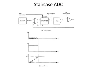
Counter Ramp Converter • Counter-ramp converters comprise a D-A converter, a single comparator, a counter, a clock and control logic • When a conversion is required a signal (conversion request) is sent to the converter and the counter is reset to zero. • The purpose of the sample-and-hold amplifier is to freeze the analogue voltage at the instant the HOLD command is issued and make that analogue voltage available for an extended period. • A clock signal increments the counter until the reference voltage generated by the D/A converter is greater than the analogue input At this point in time the output of the comparator goes to a logic 1, which notifies the control logic the conversion has finished encoder input signal digital output • The value of the counter is output as the digital value. • The time between the start and end of the conversion is known as the conversion time. • A drawback of the counter-ramp converter is the length of time required to convert large voltages. A 10 bit a/d converter will require 1024 iterations to resolve the maximum input voltage. • The worst case must be assumed when calculating conversion times
Integrating ADC Speed: Low Cost: Low Accuracy: High
References: www.ti.com/lit/an/slaa587/slaa587.pdf 1. Understanding Data Converters – SLAA013 2. ADS8318 data sheet – SLAS568A http://www.analog.com/static/imported-files/tutorials/MT-003.pdf http://www.hit.bme.hu/~papay/edu/Acrobat/DataConv.pdf Evaluating High Speed DAC Performance by Walt Kester – Analog Devices MT-013 Tutorial http://www.ni.com/white-paper/4806/en/ Home > Products and Services > White Papers > Understanding Resolution in High-Speed Digitizers/Oscilloscopes http://inst.eecs.berkeley.edu/~ee247/fa10/files07/lectures/L11_2_f10.pdf http://194.81.104.27/~brian/DSP/ADC_notes.pdf ume.gatech.edu/mechatronics_course/ADC_F10.pptx