Download
1 / 42
420 likes | 439 Views
This document package provides a comprehensive overview of the Seven-Language United Nations Headquarters Digital Recording System (DRS). It includes information on the system description, hardware and software components, software installation guide, technical details on file I/O, and more.

E N D
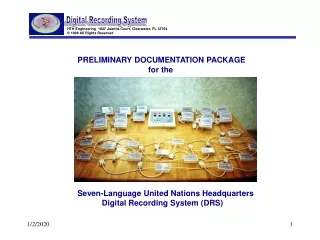
PRELIMINARY DOCUMENTATION PACKAGE for the Seven-Language United Nations Headquarters Digital Recording System (DRS)
Table of Contents Page SYSTEM DESCRIPTION…………………………………………….. 2 System Block Diagram…………………………….…………………. 5 HARDWARE COMPONENTS………………………………………. 6 DRS Control Console……………………………... 8 Start Stop DRS 4-Channel Int’fc………………….. 9 Start Stop DRS System Monitor………………….. 10 Start Stop DRS Optical Couplers………………… 11 Start Stop DRS BIT Loop Term…………………... 12 SOFTWARE COMPONENTS……………………………………….. 13 DRS Status Panel Layout…………………………. 14 DRS Workstation Recording Cntrl……………….. 15 DRS Database……………………………………... 16 DRS Network Monitor……………………………... 17 DRS Network Simulator…………………………… 18 DRS Workstation Status Panel…………………… 19 Super User-DRS Status Panel…………………… 20 Super User-DRS Database……………………….. 21 Start Stop Transcription Interface………………... 22 SOFTWARE INSTALLATION GUIDE………………………………. 23 TECHNICAL DETAILS ON FILE I/O………………………………... 26 Overall File Transfer Map…………………………. 27 DRS Status Panel File I/O………………………… 28 DRS Database File I/O……………………………. 36 DRS Workstation Stat Panel I/O…………………. 38 NOTES…………………………………………………………………. 40
Outstanding Features Robust, reliable operation: -Recordings continue even when the network goes down (and they will go down!) - Operates independently of type of computer, networking used -Computers do not depend on each other for recording -Each computer is independently controlled by light (optical couplers) eliminating electrical co-interference, spikes, glitches, and lightning-induced transients -Operates with ordinary computers and sound cards - no proprietary PCs needed. -Full, continuous hardware and software built-in-test (BIT) -Automatic, continuous monitoring of all recording computers ensures that all machines are recording reliably. -Military aircraft-style control bus operates the recording computers reliably even under adverse conditions or partial failures. Universal, Open Standards: -All files recorded in Microsoft(TM) .WAV and TrueSpeech(TM) .WAV formats, which are playable on any Windows computer -Does not require the person playing the file back to have custom hardware or software
Outstanding Features- continued Recording Compression TrueSpeech(TM) recording compression technology requires only 1/10th the file size of Technology: a standard .WAV recording, making it practical to e-mail the recordings in real-time. -File archiving is practical: A single inexpensive recordable CD-ROM holds 160+ hours of recordings. Low Life Cycle Cost: -Low initial acquisition cost -Operates independently of type of computer and networking used -Proprietary computers or “maintenance” contracts not required Longevity: -Designed to operate reliably for many years -Gold contact million-cycle switches -No active components in Control Console -Extremely low power consumption -Console control station uses an external UL-approved power module that is universally available -Optical coupled PC interfaces ensure that the computers will never be damaged from power-company voltage induced spikes or ESD(electrostatic discharge) via the Control Console -Optical coupled interfaces ensure that all hardware is “hot swappable” -Optical coupled interfaces ensure that one computer cannot cause another computer to fail
DRS Software on all 14 Recording PCs: System Block Diagram Recording PCs DRS Status Panel ARABIC ENGLISH FRENCH RUSSIAN SPANISH FLOOR CHINESE Audio Inputs (7 languages) Compressed TrueSpeech(TM) or Microsoft WAV files networked or e-mailed to Transcriptionists A A A A B A B B A B B B A B Start Stop DRS 4-Channel Language Interfaces Start Stop DRS BIT Loop Terminator 4ch SSTI 4ch SSTI 4ch SSTI 4ch SSTI 4ch SSTI 4ch SSTI 4ch SSTI 4ch SSTI 4ch SSTI 4ch SSTI 4ch SSTI 4ch SSTI 4ch SSTI 4ch SSTI Start Stop DRS Optical Couplers Opto Opto Opto Opto Opto BIT Opto Opto Opto Opto Opto Opto Opto Opto Opto Start Stop System Monitor Control Signals 4ch SSTI Built-in-test (BIT) Status Network Status Monitor Ethernet Connection for BIT Monitoring and file backup on DRS Workstation or other networked PC Recording Control DRS Workstation DRS Control Console Database Workstation Status Panel
HARDWARE COMPONENTS DRS Control Console 4-Channel Workstation System Monitor Interface 4-Channel Interfaces to recording PCs 4-Channel Interfaces to recording PCs Built in Test (BIT) Loop Terminator Optical Couplers
DRS Control Console PUSHBUTTONS and INDICATORS Record Pause End Session Erase Session HARDWARE BUILT-IN-TEST (BIT) INDICATORS: AC Power Indicator- shows that Control Console is receiving power Loop Terminated Indicator - shows that the control harness is properly connected Master EnableKey Pushbuttons are disabled if key is in the “off” position Button Pressed Indicator- Validates each pushbutton press and verifies the corresponding control signals make it through to the end of the control harness
Start Stop DRS 4-Channel Interface to Recording PCs Machine: A -One Interface required per recording computer ( 14 total for a seven-language system ) -Automatically pre-configures the recording PC to the language and Machine Type (Machine “A” or Machine “B”) -Connects to standard DB-9 Serial port on recording PC -Provides serial data and BIT commands to recording PC -Controlled via the optical coupler on the harness
Start Stop DRS 4-Channel SYSTEM MONITOR -One Interface required per DIGITAL RECORDING SYSTEM -Provides independent, real-time System Status Information (Record, Pause, Stop, and Erase) to the Workstation PC’s Database and Network Monitor (BIT) applications -Controlled by the DRS Control Console, and connected via serial port to the Workstation PC
Start Stop DRS Optical Couplers -Provides reliability, electrical isolation, and hot-swappability features -Integral part of the control harness: 2 optical couplers required for a single-language system -Ensures that each recording PC connection is totally isolated from any other recording PC and from the control console -4 opto-coupler channels provide 1,500 volts of isolation to the control harness and 3000 volts to another recording PC -Each optical channel is current-limited to the control harness bus, ensuring that any shorts or failures will not cause any other optical coupler or recording PC to fail.
Start Stop DRS Built-In-Test (BIT) Loop Terminator -Provides continuous diagnostic status (built-in-test) through the harness to the Control Console: 1) “Listens” to Record, Pause, End Session, and Erase Session pushbutton presses, and reports status through the harness back to the Control Console 2) Provides a continuous monitoring of the cable harness end-to-end
RECORDING PC’s (Machines 1-14) - Main Recording Software Progress Bar visually shows % completion of each 12 minute (nominal) recording segment DRS Status Panel Layout and Functions Large red recording symbol and flashing LED illuminates during recording for at-a-glance status Built-in-Test listens to SSTI Controller at program start up and will show fault symbol if system is not ready Configures COM Port and Language (A, C, E, R, F, S, FL) Pause Symbol illuminates if recording is paused. Real-time indicator appears below to show actual time the pause began Lets you specify any additional drive path for saving TrueSpeech files, such as a floppy or remote server New recordings are always saved to the local Recording PC’s hard drive as well as to the server drive shown here. Session Erased symbol appears when operator erases a previously specified session and turns the erase key on the control panel. Status Panel will show file to be erased before erasure. When erase key is actually turned, the SESSION ERASED symbol will go from a “gray out” condition to illuminated, and the Date/Time Erased area will show when the erase key was actually turned. Time the current session began Total elapsed time since the recording session began. When paused or ended, the ET counter stops. Current time and date, as provided by the PC’s system clock Segment time remaining. Counts down each recorded segment. Displays current recording format: TrueSpeech or Microsoft .WAV Current file name being recorded. “??” progresses from 00 to 99 during a session Session End Symbol illuminates if operator has terminated the recording session. Real-time indicator appears below to show actual time the session was ended.
WORKSTATION PC - Controls all parameters for the next Recording Session DRS Workstation Recording Control Nominal server drive letter = “r:”. If you enter another drive letter here (e.g. “s”) before clicking on UPDATE, the recording configuration file drs.cfg will be sent not only to the local hard drive root (c:\) of the machine on which you are running this Console, but also to the root of the entered drive (e.g. “s:\”). Sliding Adjustment allows you to set the amount of recording overlap between the two Recording PCs in minutes and seconds. The “Min” amount is 1 second. The “Max” limit is set in proportion to the length of the Recording time that you have set. Enter the name of the Current Recording Session here. You may also specify the Starting Segment number from 01 to 98. For example, if the Current Session Name you choose is “TEST” and 01 as your starting segment, then the first file recorded will be called “TEST01.WAV”, and then “TEST02.WAV”, and so on. The default Starting Segment is always “01” Enter the length of each Recording Segment here in whole minutes, from 1 minute to 20 minutes. Default value is set to 10 minutes. Selects whether the recording will be in standard Microsoft WAV format (11KHz, 8 bit, mono ) or TrueSpeech(TM) compressed WAV format Enter the name of a recording session here that you want to erase, and then click on the UPDATE button. Then, the next time the DRS Control Console ERASE pushbutton is physically pressed, all Recording PCs will simultaneously erase all file recordings in all languages that start with that particular name. NOTE: The Recording Control may be co-located on the DRS Workstation/Server (recommended) or it may be located on a remote, independent machine if desired Click this button once you have everything set up the way you want it. The Recording PCs will then be able to “read” the drs.cfg file that is created on the “Server Drive”
WORKSTATION PC - Maintains a Database of all Current and Past Recording Sessions DRS Database Every time the operator initiates a new Recording Session by pressing the RECORD pushbutton on the DRS Control Console, the data base automatically reads the drs.cfg file from the server, and fills in the first three columns. When the operator presses the END SESSION pushbutton on the DRS Control Console, the End Time column is automatically filled in. Database is automatically updated at this time and saved. -The database file is saved in a standard Microsoft Access (.MDB) format for easy access, review, and editing by other popular database programs. Status Indicator reads the current state of the DRS Control Console and displays it here. User may enter any data about the speech or meeting in these columns, either during or after the meeting. Move forward in records Move back in the database records Manually add or delete records to the database Manually update database by clicking here, if you have added data to the database after the recording has finished, or if you’re going back later to make corrections Search by any column for keywords, text, or boolean combinations Database Navigation Bar Date of database record (row) that is currently selected (shown by symbol) Scrollbar allow you to access Meeting Information columns easily NOTE: The DRS Database may be co-located on the DRS Workstation/Server (recommended) or it may be located on a remote, independent machine if desired
WORKSTATION PC - At-a-Glance Graphical Status of the System’s Health DRS Network Monitor Status area shows the current system operating mode Check this box if you don’t want to hear the audible alarm from the Workstation when a System Fault is detected. Fault symbol and audible alarm commence if any PC in system has a fault Overall System Health Indicator The Network Monitor application normally resides on the “Server” (i.e. Workstation), so its drive letter =C. However, the Network Monitor may be located remotely on another PC other than the Workstation if desired, and then path letter of the Server would be entered here (e.g. ‘R’) Other Indicators in the Status Indicator Area: LEDs flash on and off when recording is actually taking place on a given machine during “Recording in Progress” mode. 3). 1). Status Indicator Area for each Recording PC language pair. OK indicates that Machine “A” and “B” both are ready to record or are recording correctly. The system continuously monitors a “heartbeat” from each PC every few seconds. 2). NOTE: The DRS Network Monitor may be co-located on the DRS Workstation/Server (recommended) or it may be located on a remote, independent machine if desired During “Recording in Progress” Mode, neither Machine “A” or “B” is actively recording Machine “A” is not providing a “heartbeat” that says that it is capable of recording Yellow Arrow shows location of the machine that is not ready.
WORKSTATION PC - Simulates Entire Network for Troubleshooting or Partial Language Operation Simulated LEDs flash when Recording Checkboxes are checked to simulate the “heartbeat” of a real Recording PC Machine The Network Simulator application normally resides on the “Server” (i.e. Workstation), so its drive letter =C. However, the Network Simulator may be located remotely on another PC other than the Workstation if desired, and then path letter of the Server would be entered here (e.g. ‘R’) Fault Simulator Area allows you to simulate a “bad” Recording PC for troubleshooting purposes. Checking the box means that the PC is READY. Simulates the SYSTEM MONITOR box and DRS Control Console for testing purposes. -PARTIAL LANGUAGE OPERATION: For example, suppose the Chinese machine is not intended to be used, but the Network Monitor will continue to beep and show a fault condition. To eliminate this, launch the Network Simulator and un-check every box. Now add checkmarks to Chinese Recording “A” and Ready/Not Ready Chinese “A” and “B”. The Network Monitor will be “fooled” into thinking that the Chinese Machine is running normally, and will not show any alarms or faults during your recording session.
WORKSTATION PC - Status Panel Shows Current State of Control Console Status Panel for Workstation Workstation PC Record, Pause, Session Over and Session Erased status sent to root of c:\ on the Server. (Workstation). This status is used by the DRS Network Monitor and DRS Database to obtain an independent check of the Network actions in progress. -The DRS Workstation Status panel is independent of the rest of the Digital Status System, and reads the user’s button presses from the DRS Control Console. -Independent status is provided by the DRS 4-Channel System Monitor interface hardware, that is connected to the Workstation. DRS 4-Channel System Monitor NOTE: The Workstation Status Panel must be co-located on the DRS Workstation/Server
“Super User” Features DRS Status Panel - To operate in Super User mode: 1). Click and drag the mouse pointer on the bottom edge of the DRS Status Panel Window to expand it vertically. 2). Check the small box next to “Super User”. Instantly Update Drive Letters without Re-running the DRS Status Panel Application Current drs.cfg data as read from the Server by the DRS Status Panel Observe low-level Windows OS Messaging here Real-time event log can be viewed and scrolled Erases all copies of recordings that are on the Server with the current File Name Print event log to printer Erase all Recordingsin all languages on this Recording PC with the File Name currently chosen. Software Flag Diagnostics Parameters (Real Time)
“Super User” Features DRS Database - To operate in Super User mode: 1). Click and drag the mouse pointer on the bottom edge of the DRS Status Panel Window to expand it vertically. 2). Check the small box next to “Super User”. View total number of records that are already saved to the hard drive. Scroll through database records and delete them Enter any date, filename and start time then click the button to force entry of a recording date, filename, and start time. Enter any end time and then click the button to force entry of a recording end time.
TRANSCRIPTION STATIONS (Remotely Located on the Network, or Overseas Connected by E-Mail) Start Stop Transcription Interface --Version 6.02 New Features for Version 6.02 File name and path are displayed in the title bar Total recording length and file size is displayed in New mode lets user select whether recordings will overwrite or insert into a previous recording Two-Way Slider Control: 1) User can position the WAV file instantly to any point in the recording by sliding the control handle with either mouse or left & right keyboard arrow keys 2) Slider button moves from left to right as the recording progresses from start to finish • Real Time Display: The SSTI reads the file date time stamp calculates real time based on recorded file length and position within the recording, and displays it to the user. • For UN Digital Recording System (DRS) use, the AccuStamp mode displays real time based on the DRS’s accurate start time stamping of each recorded segment. • For non-DRS generated WAV files, real time is an estimate, based on the assumption that the recording was saved to disk after the recording was completed.
Installation Guide for 7-language DRS + Server/Workstation 1) Insert the Installation CD-ROM into the Server/Workstation PC, and then double-click on the WORKSTATION subdirectory to view the installation program directories: * DRS Server/Workstation INSTALL CD-ROM * 2) Run “setup.exe” for each installation program. The order of installation does not matter. Follow the on-screen instructions The “Server” default is set up as “r:\”, but may be configured by the user to another drive letter. * = Note: This is the only program that must reside on the Server. The other programs may be installed on a remotely located ( but network connected) workstation, if desired, since each of these programs can be configured to point to the Server path (e.g. “R”).
3) Insert the Installation CD-ROM into each of the 14 Recording PCs, and then double-click on the RECORDING PCs subdirectory to view the DRS STATUS PANEL installation program directory: Recording PCs A B INSTALL CD-ROM 4) Run “setup.exe” for the installation program. Follow the on-screen instructions 5) Installation is now complete.
Overall File Transfer Roadmap CONTINUOUS MONITORING (“Heartbeat”) Files Recording PCs (One language shown) Example Output from One PC: “I’m Ready to Record” Heartbeat File Optional Floppy Save for TrueSpeech Recordings “I’m Recording Now” Heartbeat File Floppy can also be used to manually load drs.cfg if network is down DRS Status Panel SW on each Recording PC Network Recording PCs A B Continuously Created Speech Files (e.g. “Esc768A.wav”) are also sent over network for Backup on the Server ALL Speech files saved to local PC hard drive Log Files are Created after Session is Over (e.g. “E_A.log”) and saved on each PC hard drive Log Files Created after Session is Over (e.g. “E_A.log”) are also sent over network for Backup on the Server C:\Windows\drspan2.ini C:\Windows\drsdefault.cfg Server’s drs.cfg file isread by each Recording PC’s DRS Status Panel Software (e.g. “Esc768A.wav”) Recording Control Created by the Recording Control Program (root of server) C:\ DRS.CFG C:\DRS\ *=Backup Directories of Speech Files from all 14 Recording PCs on Server * Continuous Monitoring Files Stored Here from Recording PCs Database DRS Server/Workstation * * Database File Stored here “drs2.mdb” * DRS Server/Workstation * Start Stop System Monitor From DRS Control Console 4-ch SSTI * Workstation Status Panel * Logfile backup from each of the 14 Recording PC’s C:\Windows\ Stores the Server Drive Letter for the Database Program e.g. “c” “drs_db.ini” Broadcasts current Control Console Status (File=“*.now”, where * = Record, End, Pause, Erase) C:\ = (“R:\” as seen by the rest of the network) DRS Network Monitor: Listens to “Heartbeats” from Recording PCs
1) The DRS Status Panel executable (“DRS Status Panel.exe”) when launched, will look for the server’s “drs.cfg” file, and will be looking for it to be on drive “R:\” in the root level. If it can’t find it, it will then give dialog boxes asking you if you want to use the default local cfg. File. The DRS Status Panel should look like this (except for the filenames, which may be different than shown):
2) When the DRS Status Panel starts running, it creates the following subdirectories on both the local recording PC under “C:\DRS”, as well as on the server’s hard drive, under “R:\DRS:”. Recordings are initiated as a series of sequentially numbered file names when the user presses “RECORD” on the console. The files are automatically copied as they are created to both the local recording PC’s hard drive, as well as to the Server’s hard drive. The File Naming convention is as follows: 2 3 1 4 Ahello01.wav File name example 1. First letter represents the language or audio source of the recording: A=Arabic, C=Chinese, English, “_” (underscore) =Floor, F=French, R=Russian and S= Spanish. 2. Session Name entered from the DRS Workstation Console: Up to 5 alphanumeric characters long. 3. Sequential recording segment number. Automatically assigned by the DRS recording system. Odd numbers (01,03,05…) come from Machine “A”, while even numbers (02, 04, 06…come from Machine “B”.4. File name extension: “.wav for recordings, or “.log” for Logfiles.
3) LOGFILES During a recording session, a “log file” is created. At the end of the recording session, the logfile is automatically copied to the directory “C:\DRS\Logfiles” on both the local recording PC, as well as to the server. The file naming convention is: 2 3 1 4 AhelloA.log 1. First letter represents the language or audio source of the recording: A=Arabic, C=Chinese, English, “_” (underscore) =Floor, F=French, R=Russian and S= Spanish. 2. Session Name entered from the DRS Workstation Console: Up to 5 alphanumeric characters long. 3. Source of the logfile: Machine “A”= “A”, and Machine “B”=“B” 4. File name extension: always “.log” for Logfiles. The logfiles are created in plain-text format (ASCII) and can be read with the Notepad application in Windows. The logfiles provide date-time event stamps and document every action the user or the DRS recording software generated during a recording session. The logfiles are compact, and can be viewed or e-mailed when technical support is required.
4) Configuration and INI Files A.) “DRSPAN2.INI” -Used by the DRS Status Panel During installation, this file is copied to the Windows directory, normally C:\Windows. The file is automatically updated each time “DRS Status Panel.exe” runs, and is saved upon exit or shutdown with the most current configuration. (ASCII TEXT FILE FORMAT) File date time stamp of the last executed recording’s “drs.cfg”, a configuration file generated by the DRS Recording Console. 1,”4/30/98 3:09:10 AM”,”r”,“c”,“c” Hard Drive Letter that the DRS Status Panel software will use for default saving of all Microsoft .WAV and TrueSpeech(TM) .WAV recording segments on the Recording PC Data delimiters = commas (always present) Com Port Number (notice no quotes!) Extra Drive Letter that the DRS Status Panel software will use to save TrueSpeech (TM) files to an extra path, such as to a floppy, on the Recording PC, or a remote network backup path (e.g. “m”) Server Drive Letter that the DRS Status Panel software will use to search for and load the file “drs.cfg”
4) Configuration and INI Files (continued) B.) “DRSDEFAULT.CFG” -Used by the DRS Status Panel During installation, this file is copied to the Windows directory, normally C:\Windows. It is a backup (data source) file that is copied to the local hard drive root and renamed as “drs.cfg” (c:\) and used in cases where the DRS Status Panel cannot find the server’s hard drive root (e.g. “r:\) copy of the file “drs.cfg”. The DRS Status Panel will alert the operator that it can’t find the server file drs.cfg, and will ask if they want to load the “default” configuration for this recording, or else manually copy a “drs.cfg” file in the root of the local hard drive via floppy or otherwise. (ASCII TEXT FILE FORMAT) "deflt","deflt",720,"TrueSpeech WAV (TM)",120, “01” Exact Text String as shown tells the DRS Status Panel application to use TrueSpeech. OR... “Microsoft WAV (TM)” to use the un-compressed recording format Recording Overlap Total in Seconds (nominally 2 minutes) Starting Segment Number as Set by the User in the Recording Control Panel on the Workstation 5-letter name of the recording session with a file name of “deflt” Total recording time in seconds, a nominal time of 10 minutes + 2 minutes of overlap: (60 seconds x 10 minutes) + (60 seconds x 2 minutes) = 720 seconds total 5-letter name of the ERASE SESSION file name = “deflt”
4) Configuration and INI Files (continued) C.) “DRS.CFG” -Generated by the DRS Recording Control Software This file is generated whenever the operator clicks on the UPDATE button on the DRS Recording Control application. The nominal drive letters to which this generated file is sent = “r:\” and the local hard drive “c:\”. If you enter another drive letter in the “Server Drive Letter” box (e.g. “s”) before clicking on UPDATE, then recording configuration file drs.cfg will be sent not only to the local hard drive root (c:\) of the machine on which you are running the DRS Recording Control application, but also to the root of the entered drive (e.g. “s:\”). (ASCII TEXT FILE FORMAT) ”hello",”sc768",720,"TrueSpeech WAV (TM)",120, “01” Starting Segment Number as Set by the User in the Recording Control Panel on the Workstation Exact Text String as shown tells the DRS Status Panel application to use TrueSpeech. OR... “Microsoft WAV (TM)” to use the un-compressed recording format Recording Overlap Total in Seconds (nominally 2 minutes) 1 to 5letter name of the recording session with a file name of “hello” Total recording time in seconds, a nominal time of 10 minutes + 2 minutes of overlap: (60 seconds x 10 minutes) + (60 seconds x 2 minutes) = 720 seconds total 1 to 5 letter name of the ERASE SESSION file name = “sc768”
4) Configuration and INI Files (continued) D.) BIT FILES -Generated by the DRS Status Panel These 1-byte long files are automatically generated and deleted on the Server’s r:/DRS/BIT subdirectory about once per second to form a “heartbeat” signal whenever the DRS Status Panel is running. This heartbeat is detected by the Network Monitor and reports the health status of each Recording PC: “I’m Healthy and Ready to Record” file: F_INITBIT_A.ok Language (e.g. French) Machine “A” or “B” Identifier “I’m Actually Recording Now” file: F_BIT_A.on Language (e.g. French) Machine “A” or “B” Identifier
Configuration and INI Files: A.) “drs_db.ini” FILE -Generated and read by the DRS Database This file normally resides in the c:\Windows directory of the PC in which the DRS Database application is stored. It tells the Database program the path where to look for the database itself, stored in the /DRS/Database subdirectory as “drs2.mdb”. “c” File contents (ASCII): B.) “drs2.mdb” FILE -Read and modified by the DRS Database This file normally resides in the (server drive:)/DRS/Database subdirectory as“drs2.mdb”. It contains the entire database for all Recording Sessions. It is a standard Microsoft (TM) Access Format Database file, and may be read or edited by Microsoft Access or other applications that can read the .mdb format.
DRS WORKSTATION STATUS PANEL FILE I/O
Communication File: The Workstation Status Panel’s function is to independently communicate the current state (last button pressed) of the DRS Control Console. This information is communicated to the DRS Network Monitor and DRS Database applications via the (server drive:)/DRS/BIT subdirectory. A single 1-byte long file is dynamically created and deleted to reflect the current state of the DRS Control Console: “Record.now” “Erase.now” “End.now” or “Pause.now” One and only one of these files will appear in the (server drive:)/DRS/Bit subdirectory at a time. R:/DRS/BIT/
NOTES 1). Logfiles are not erased; they accumulate until you manually erase them. If the same session name is used over again (another recording is made with the same file name as previously, using the UPDATE button to purposely record on top of the old one), the logfile will overwrite the previous logfile of the same name when the recording is over 2) Server Recordings will not be erased. 3) If a new recording session is initiated without changing the session name first, the DRS Status Panel will refuse to record over the existing session. However, if you click on the UPDATE button in the DRS Recording Control panel without changing the session name, then the DRS Status Panel will allow you to record over the existing files. If you do this, please note that currently the software overwrites the existing recordings on a one-by-one basis. It does not carte-blanche erase the previous recording session files before it begins. 4) Be sure that the recording PCs have had Windows (TM) installed with all multimedia options checked. To verify, go to START, SETTINGS, CONTROL PANEL, ADD/REMOVE PROGRAMS, then WINDOWS SETUP. Make sure that all MULTIMEDIA options have been installed & checked (Click on DETAILS). 5) Keyswitch Failure Backup- Should the key-operated switch on the DRS Control Console ever fail, there is a back-up switch located on the bottom of the DRS Control Console unit. Using a thin long object (such as a pencil), push through the small hole until a “click” is heard. The internal switch will now be in the “on” position, overriding the keyswitch, even if the keyswitch was off. Note that once this internal switch has been thrown “on”, the DRS Control Console will remain “ON” continuously, and the Record, Pause, End, and Erase pushbuttons will always be active if pressed. 6) The Database File “drs2.mdb” is located on a floppy disk included with the Installation CD-ROM. Please copy this database sample file to the Server’s c:\DRS\Database subdirectory before launching the DRS Database application.