Download

1 / 25
250 likes | 406 Views
LBCB Servo Control System. February 17, 2006. Based on Work by Narutoshi Nakata Ph.D. Candidate. Outline of Presentation. Introduction Load and Boundary Condition Boxes (LBCBs) Control Objectives Control System Architecture Feedback Control Loops Internal Analog Loop

E N D
LBCB Servo Control System February 17, 2006 Based on Work by Narutoshi Nakata Ph.D. Candidate
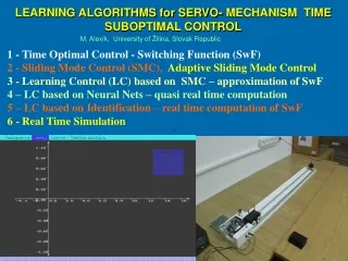
Outline of Presentation • Introduction • Load and Boundary Condition Boxes (LBCBs) • Control Objectives • Control System Architecture • Feedback Control Loops • Internal Analog Loop • Middle Convergence Loop • Mixed Load/Displacement Loop • Displacement Control Example • Mixed-Mode Control Example • Hybrid Simulation
Load and Boundary Condition Boxes (LBCBs) Features • 6DOF Boundary Condition Generator • Designed for the Pseudo Dynamic Testing • Servo Hydraulic Control System • 6 Actuators • Servo Valve, LVDT and Load Cell for each actuator Full-scale LBCB 1/5th-scale LBCB
Substructure Test Displacement Load Control Objectives Mixed Load / Displacement Control Earthquake Event Gravity load Earthquake Excitation • To simulate gravity load effects on the specimen in substructure tests • To impose any combination of load or displacement in all three translational and rotational axes
z x y Control Objectives Challenges in Mixed-mode Control Cartesian Space Actuator Space x,y,z, , , x1,x2,y,z1,z2,z3 Cross Coupled Fx1,Fx2,Fy,Fz1,Fz2,Fz3 Fx,Fy,Fz,Mx,My,Mz y1 • Cross-coupling does not allow conversion from mixed load / displacement Cartesian commands into actuator commands. • Direct load control is not practical. • Mixed-mode control is dependent on the properties of the specimen. x2 z3 x1 z1 z2 Mixed-mode Control Algorithm
Control System Architecture Major Components Equipment Software (Digital) Hardware (Analog) Control Board 1 Actuator X1 Actuator X2 NI SCXI -1001 (A/D, D/A Converter Modules) & PCI-6052E Control Board 2 LBCB Operation Manager (Servo Control Software) Actuator Y1 Actuator Z1 Control Board 3 Actuator Z2 Actuator Z3
Servo Controller Feedback Control Loops • Internal Loop • Displacement Control in Actuator Level • Middle Convergence Loop • High-precision Cartesian Displacement Control • External Mixed-mode Loop • Jacobian-based Mixed-mode Control Algorithm
Internal Loop Feedback Control Loops Feedback Control System Actual Output Response Desired Output Response Command Error + Actuator Controller - x1d x1m Measurement LVDT, Load Cell Control PC Serve Valve
Internal Loop Feedback Control Loops Feedback Control System Actual Output Response Desired Output Response Command Error + Actuator Controller - x1d x1m Measurement PID Controller KP + Error Command + KI + KD
Internal Loop Feedback Control Loops PID Controller KP + Error + Command KI + KD KD KP KI Desired Value Desired Value Desired Value KD:High KD:Tuned KD:Low KP:High KP:Tuned KP:Low KI:High KI:Tuned KI:Low Initial Value Initial Value Initial Value sec sec sec
Internal Loop Analog Loop on Control Board Actuator Displacement Control + Command Amp Valve Compensator Controller Servo Valve DCV - Servo Error DCV LVDT ACV DCV Demodulator Signal Conditioner LVDT DCV Excitation ACV Load Cell DCV Signal Conditioner Load Cell DCV Excitation DCV Control Board
Middle Convergence Feedback Loop Process in Time Domain • Idle: Ready for the Next Target • Ramp: Executing Incremental Command • Convergence: Reducing Steady State Error • Hold: Sampling and Averaging Data Control Unit yt(N) Command yt(N) Measured ym(N) yc(t) ym(t) yr(t) Idle Ramp Hold Idle Convergence Time Step N Step N+1
Middle Convergence Feedback Loop Implementation Architecture Analog Loop (Control Board) + + Command Cartesian Displacement Command Servo Valve Controller Cartesian To Actuator NI SCXI - Discrete PID D / A Converter LVDT LVDT - Servo Error Load Cell Load Cell Middle Convergence Loop (Digital) X1 Actuator Six Actuators Measured Cartesian Displacement Actuator To Cartesian Measured Cartesian Force + Command Servo Valve Controller - LVDT LVDT Servo Error A / D Converter Load Cell Load Cell Z3 Actuator
Mixed Load/Displacement Feedback Loop Implementation Architecture Analog Loop (Control Board) + + Command Cartesian Displacement Command Servo Valve Controller Cartesian To Actuator NI SCXI - Discrete PID D / A Converter LVDT LVDT - Servo Error Load Cell Load Cell X1 Actuator Cartesian Mixed-mode Command Stiffness Jacobian Six Actuators Middle Convergence Loop (Digital) Actuator To Cartesian + Command External Mixed-mode Jacobian Loop (Digital) Servo Valve Controller - LVDT LVDT Servo Error A / D Converter Load Cell Load Cell Z3 Actuator
Substructure Test z x y Displacement y1 x2 Load z3 x1 z1 z2 Mixed Load / Displacement Control Challenges Cartesian Space x,y,z, , , Fx,Fy,Fz,Mx,My,Mz In Mixed-Mode Control, the required displacements are dependent on the uncertain stiffness characteristics of the test structure. Cross-coupled Actuator Space x1,x2,y,z1,z2,z3 Fx1,Fx2,Fy,Fz1,Fz2,Fz3
Mixed Load / Displacement Control Control Algorithms & Simulation • Approach Displacement-based mixed-mode control scheme • Task Based on mixed-mode Cartesian commands, specify Cartesian displacements and then convert them into actuator displacement commands • Algorithm Flexibility Jacobian-based algorithms LBCB Simulator Simulation program has been developed for testing, debugging and improving mixed-mode control algorithms.
Displacement Control Test Rubber Specimen Objectives • Check displacement control capability with specimen • Monitor vertical force under pure lateral loading Translation X Initial Force Z0 Control Pattern X : Sin Wave (2 cycles, 0.7 inch, 200steps) Fz0 : 120 (lb) Initial Vertical Force Y, Z, Rx, Ry, Rz : constant
Mixed-mode Control Test Rubber Specimen Objectives • Check mixed-mode control capability • Monitor vertical displacement to keep constant force • Check Jacobian Updates Translation X Control Force Z Translation Z Control Pattern X : Sin Wave (2 cycles, 0.7 inch, 200steps) Fz : 120 (lb) constant (controlled) Y, Rx, Ry, Rz : constant
Multi-axes Load Control Test Four-axes of load control Target loads Measured loads
Screen Image Updated Jacobian
Tele-Control Capability NTCP (NEES Tele-Control and Operation Protocol) Tele-Control Application NTCP LBCB Operation Manager • Network Gateway Program • Initially Developed by Paul Hubbard@neesit • Customized and Compiled for LBCB Application