Download
1 / 14
140 likes | 319 Views
C alibration of the gain and measurement of the noise for the apv25 electronics. K. Gnanvo , N. Liyanage , C.Gu , K. Saenboonruang From INFN Italy: E. Cisbani , P. Musico. Experimental setup put in place at UVa to

E N D
Calibration of the gain and measurement of the noise for the apv25 electronics K. Gnanvo, N. Liyanage, C.Gu, K. Saenboonruang From INFN Italy: E. Cisbani, P. Musico
Experimental setup put in place at UVa to • Measure the gain of two apv25 based readout electronics: Scalable Readout System (CERN, RD51) and MPD (INFN Italy for SBS) • Measure the apv channels rms noise and estimation of the ENC from the apv gain measurement • Comparison of the performances of the two systems
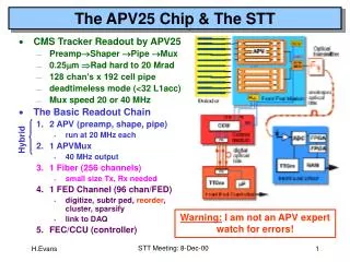
APV25 MPD and SRS system • Multi Purpose Digitizer (MPD) • P. Musico, INFN Italy • More than 2.5K Channels at UVa • Scalable Readout System (SRS) • H. Muller, CERN, RD51 • 2048 channels at Uva
APV2 on SBS GEM prototype SRS MPD Analog signal 25 ns time frame
APV25 and ADC configuration for MPD and SRS systems • We have almost the same configuration parameters for the two systems • Different performances of the two electronics can be related to some differences in hardware that Paolo has identified: • protecting diode in the VCC line of the INFN card • input capacitance 47 pF vs. 1 pF in SRS • 1 Mresistor to ground in the SRS input lines • external biasing in INFN card vs. internal biasing in SRS (this affect the values of the APV parameters for the optimal working point) SRS MPD
Apv25 Gain: MPD vs SRS Gain calibration with 3.3pF and 10pF Gain calibration for SRS and MPD
Study of the noise (rms of the apv25 channels) • Typical rms for each of the 128 channels of a given APV cards from a pedestal run and for both MPD and SRS • This rms is obtained after common mode correction of the baseline • The common mode correction reduce the rms by • a factor 2 for apv25-MPD (basically from ~ 40 adc counts to ~ 20) • A few adc counts for apv25-SRS (from ~8 adc counts to 6.5-7) APV25-MPD on GEM readout strips APV25-SRS on GEM readout strips
Where do the hot channels come from for apv25-MPD electronics • Hot channels appears in some of the apv cards • Sometimes come from the noisy strips or bad connection with the adapter • Not always from the GEM strips nor is it alway coming from the flex adapter • We are still studyin this effect APV25-SRS disconnected APV25-MPD With Flex adapter APV25-SRS on GEM readout strips
RMS noise and Equivalent Noise Charges for the 13 apv25 FE cards • Noise in ADC counts is 3 × bigger for MPD (~20 ADC channels) than SRS (~7 ADC channels) • When translated into ENC, it becomes a factor ~10 because MPD has a gain 3 to 4 times higher than SRS MPD: RMS noise 13 cards disconnected Mean ENC ~ 11245 MPD: RMS noise Mean ENC = 16776 SRS: RMS noise Mean ENC = 1462 e-
SRS: GEM Readout strip Capacitance effect on the noise RMS distribution over 13 cards Long narrow strips on GEM readout board Short wide strips on GEM readout board
SRS: Effect of the number of apv25 time frames on the noise 3 timeslots data 18 timeslots data
APV25 Readout time Buffer length 192 samples : 4.8 us Look back 160 samples 32 samples reserved for event readout Look back 160 samples 4 us APV readout time : t_APV = 141 x number_of_sample / 40 MHz t_APV (1 sample) = 3.7 us. Max rate APV front end : 270 KHz in 1 sample mode 90 KHz in 3 samples mode Will be triggered by coincidence trigger around 50 KHz