Download
1 / 73
740 likes | 940 Views
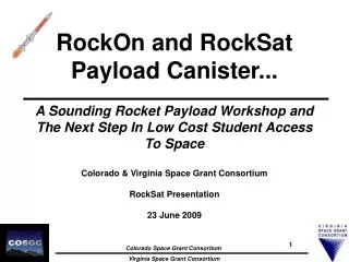
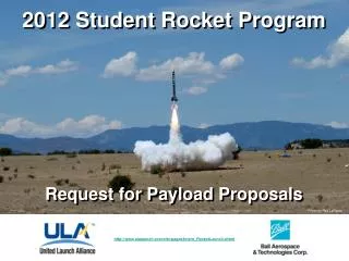
RockOn and RockSat Payload Canister... A Sounding Rocket Payload Workshop and The Next Step In Low Cost Student Access To Space Colorado & Virginia Space Grant Consortium Design Review March 19, 2010 1:00 PM EDT. 1.0 Launch Vehicle Layout and Amenities “What/Who is flying”?

E N D
RockOn and RockSat Payload Canister... A Sounding Rocket Payload Workshop and The Next Step In Low Cost Student Access To Space Colorado & Virginia Space Grant Consortium Design Review March 19, 2010 1:00 PM EDT
1.0 Launch Vehicle Layout and Amenities “What/Who is flying”? 2.0RockSat-W ~ RockOn! “The Standard RockOn payload” 3.0RockSat-C Payloads “What’s inside each canister”? 4.0 Week of Launch Schedule “What’s the plan”? 0.0 Presentation Overview
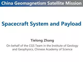
RockOn 2010 + RSPC Section Payload Access Section Motor Adapter RSPC Section Nose Cone PL9 PL8 PL7 PL5 PL4 PL3 PL2 PL1 PL6 Command Line Customer Manifest: Team 1: CSU/UNC Team 2: Temple/WVU/Louis Team 3: Minn (D/S)/Wyoming Team 4: Purto Rico (D/S) Team 5: CU Boulder/VT Team 6: RockOn 2010 Team 7: RockOn 2010 (Camera) Team 8: RockOn 2010 Team 9: RockOn 2010 Team 10: Menominee • Forward Amenities: • 4 Activation Relays • 3 lines per relay • 4 Optical Ports • 2 Ram Ports • 2 Static Ports • Aft Amenities: • 1 Activation Relay • 3 lines per relay • 2 Dust Detector Ports • 2 Optical Ports (one easily changed to static) • 2 Leedex Switches • 12 lines per Leedex • ** Note: The optical ports in the lower section are designed such that an atmospheric port can be inserted in its place with minimal effort. 1.0 Terrier Orion Layout Atmospheric Port Dust Detector Optical Port
0.SYS.1: All payloads shall be designed such that Wallops will always know its status as active or inactive (current flowing/not flowing). 1.SYS.1: Payloads wishing to activate early shall be designed such that Wallops can activate and deactivate the payload or subsections of the payload via a single set of RBF wires. 1.SYS.2: Payloads wishing to activate at launch shall be designed with two opens in the system such that activation occurs if and only if Wallops has closed the RBF connection and the G switch has been depressed. Activation Summary Table 1.1 Activation Requirements and Summary
RockSat-W RockOn!
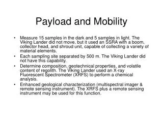
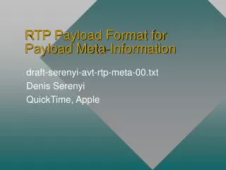
2.0 Workshop Payload Overview The mission of RockOn is to teach university faculty and students the basics of rocket payload construction and integration. RockOn also acts as the first step in the RockSat series where workshop participants return the following year to design, build, test, and fly their own experiment. The RockOn payload is designed to capture and record 3-axis accelerations, pressure, temperature, and radiation counts over the course of the mission. Main Computer Board Geiger Counter (Science) Code—Embedded C Accelerometer board Over the course of 3 days! 7
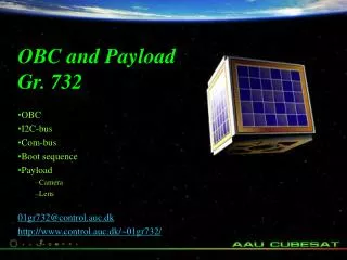
2.1 Workshop Payload FBD RBF (Wallops) RockSat-W Functional Block Diagram Power 2x9V Supply Batteries G-Switch AVR Board 5V Regulator Flash Memory Pressure Transducer Z Accelerometer AVR Microcontroller ADC X / Y Accelerometer Temperature Sensor Z Accelerometer Geiger Counter Data Power Z-Accelerometer Board Geiger Counter 8
2.2 RockSat-W Status Updates % Complete Canisters Machined Environmental Testing Electronics Acquired/Assembled Structural Hardware Acquired Kits Assembled 9
10 Universities from across the United States will fly RockSats in June! PL9 PL8 PL7 PL6 PL5 PL4 PL3 PL2 PL1 3.0 Who’s Flying? CSU Conceptual Payload Design University of Minnesota Conceptual Payload Design
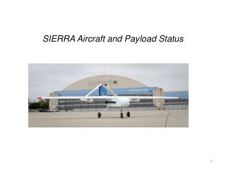
March 19th, 2010 NASA Wallops Update
Introduction and Background Project Layout Schematics Future Work/Testing The Problem and Proposed Solution No current, acceptable solution exists to determine liquid volume in a tank exposed to microgravity, without some form of stratification, tank stirring or spacecraft acceleration. An optical mass gauge is a viable option Normal Gravity Microgravity
Introduction and Background Project Layout Schematics Future Work/Testing Solid Model of Flight-Ready Prototype Tanks Laser Diode Mount Actuator Piston Solenoid Valves Gas Cell
Introduction and Background Project Layout Schematics Future Work/Testing Prototype Assembly
Introduction and Background Project Layout Schematics Future Work/Testing Functional Block Diagram Liquid Systems Data Handling and Control Battery @ 7.2V DC Power Systems Gas/Water Tank 1 Gas/Water Tank 2 G-Switch 4x 4GB Redundant uSD Flash Memory Latching Relay Linear Actuator / Piston Chamber Power Board: 16x 1.1-1.5 1A Channels Valve 1 Valve 2 Custom Atmel Board HeNe Power Supply Optical Systems Fiber Bench / Gas Chamber Beam Splitter 1 635nm HeNe Laser Legend Power Data Single Mode Fiber Beam Splitter 2 Photodiode Detector Gas Tubing Laser Beam
Introduction and Background Project Layout Schematics Future Work/Testing Data Handling and Control
Introduction and Background Project Layout Schematics Future Work/Testing Power
Introduction and Background Project Layout Schematics Future Work/Testing Commands and Sensors • Communication layout • Power on sequence G switch activation With latching relay Atmega8515 brings up each of the 16 1A regulated lines Atmega2561 starts all data logger communication First read of sensors
Introduction and Background Project Layout Schematics Future Work/Testing Testing Reference Fringe Shift ≈ 15 fringes V(t) Time [arbitrary]
Introduction and Background Project Layout Schematics Future Work/Testing Testing Tank 1 (empty) Fringe Shift ≈ 5.75 fringes V(t) Time [arbitrary]
Introduction and Background Project Layout Schematics Future Work/Testing Testing Tank 2 (containing water) Fringe Shift ≈ 7 fringes V(t) Time [arbitrary]
Introduction and Background Project Layout Schematics Future Work/Testing Status / Summary % Complete Mechanical Elements Designed Mechanical Elements Fabricated Mechanical Elements Tested Electrical Elements Design Electrical Elements Fabricated Electrical Elements Tested Software Written Software Tested Subsystem Testing System Integration Full System Testing
3.2.1 UNC: Who’s in the Can? PL9 PL8 PL7 PL6 PL5 PL4 PL3 PL2 PL1 The University of Northern Colorado: Team Members: Sage Andorka(PM) Dan Welsh Zack Sears Maurice Woods IIIMotoaki Honda SloshSAT Mission Overview: The purpose of the mission is to determine the validity of an analytical method developed to describe liquid slosh in fuel tanks. SloshSAT hopes to record data that will give a solution to the analytical model.
3.2.2 UNC: FBDs PL9 PL8 PL7 PL6 PL5 PL4 PL3 PL2 PL1 The University of Northern Colorado Functional Block Diagram: Canister ↑ Movement ↓
3.2.3 UNC: Electronic Schematic PL9 PL8 PL7 PL6 PL5 PL4 PL3 PL2 PL1 The University of Northern Colorado Electronic Schematic:
3.2.4 UNC: Status Updates PL9 PL8 PL7 PL6 PL5 PL4 PL3 PL2 PL1 The University of Northern Colorado Status Updates: % Complete Mechanical Elements Designed Mechanical Elements Fab Mechanical Elements Tested Electrical Elements Design Electrical Elements Fab Electrical Elements Tested Software Written Software Tested Picture ?? Subsystem Testing System Integration Full System Testing
3.2.5 UNC: Issues and Concerns PL9 PL8 PL7 PL6 PL5 PL4 PL3 PL2 PL1 The University of Northern Colorado Issues and Concerns: 1.) Concerned about Accelerometer leads creating a spring effect. 4.) Double checking that the Galden is okay for use. Picture ?? Picture ??
3.3.1 Temple: Who’s in the Can? PL9 PL8 PL7 PL6 PL5 PL4 PL3 PL2 PL1 Temple University: Team Members: Dr. John Helferty Dr. Shriram Pillapakkam Jinyan Chen Billy Cheng Brittany Gray Charles Wright Jonathan Childs (Dr. Pillapakkam and Jon are not pictured) Rock It Rocket Mission Overview: The mission of Rock It Rocket is to design, build, and test a passive vibration suppression system to counteract launch vehicle vibrations. We will use two identical vibration measurement systems to test and compare our design. One system will be rigidly mounted to the canister, while the other system will be passively damped.
3.3.2 Temple: FBDs PL9 PL8 PL7 PL6 PL5 PL4 PL3 PL2 PL1 Temple University Functional Block Diagram: Voltage Regulator 9V Li Ion Batteries RBF Wiring G-Switch 3.3V 5V ISP (Data retrieve) VL Vcc Flash memory Microprocessor Logic Level Translation Data ADC Data In Data out Level Shifter PC ISP (Programming code ) Coding Micro Data Analysis Legend 9V XL, YL, XH, YH, ZL, ZH Accelerometers 5V 3.3V Data
3.3.3 Temple: Status Updates PL9 PL8 PL7 PL6 PL5 PL4 PL3 PL2 PL1 Temple University Status Updates: % Complete Mechanical Elements Designed Mechanical Elements Fab Mechanical Elements Tested Electrical Elements Design Electrical Elements Fab Electrical Elements Tested Electrical Prototype Vibration Testing Software Written Software Tested Subsystem Testing System Integration Full System Testing Electrical Schematic
3.3.4 Temple: Issues and Concerns PL9 PL8 PL7 PL6 PL5 PL4 PL3 PL2 PL1 Temple University Issues and Concerns: 1.) We have yet to complete dynamic analysis of proposed plate placement design. 2.) Lead time on our dampers is longer than expected. 3.) Ensuring proper operation of coding.
3.4.1 WVU: Who’s in the Can? PL9 PL8 PL7 PL6 PL5 PL4 PL3 PL2 PL1 West Virginia University Team Members: Nick Barnett Rob Baylor Luke Bowman Marc Gramlich Caraline Griffith Steve Majstorovic Denzel Parks Ben Pitzer Kevin Tewey Evan Wolfe Yu Gu DJ Pisano Dimitris Vassiliadis WVU Rocketeers Mission Overview: The mission of WVU RockSat is to design, build, and test three atmospheric and plasma physics experiments: a temperature measurement, a vector magnetic field probe, and a radio-sounding plasma-density measurement. We expect to obtain height profiles for the first two variables and get a proof of concept for a novel plasma measurement.
3.2.2 Canister 1: FBDs West Virginia University Functional Block Diagram Main Board Radio Board Power Supply G Power Supply Optical Port RBF G RF in ANT Regs Regs Flash Memory Fixed-f Pulse Tx ANT Pre-amp & Power filter uMag RF out Super het Inertial Sensor LO Swept-f Pulse Tx ANT uController IF A D C Thermistor Amplifier uController Z Accel A D C Flash Memory Gyro Legend Power C&DH Sensors Power flow Comm/Con Data flow
3.4.3 WVU: Status Updates PL9 PL8 PL7 PL6 PL5 PL4 PL3 PL2 PL1 West Virginia University Status Updates: % Complete Mechanical Elements Designed Mechanical Elements Fab Mechanical Elements Tested Electrical Elements Design Electrical Elements Fab Electrical Elements Tested Software Written Software Tested Subsystem Testing System Integration Full System Testing
3.4.4 WVU: Issues and Concerns PL9 PL8 PL7 PL6 PL5 PL4 PL3 PL2 PL1 West Virginia University Issues and Concerns: 1.) Transmitter frequency range is limited compared to possible extremes of plasma density variability 2.) Tests needed to show how well receiver can distinguish between plasma echo and canister reflections 3.) Receiver demodulator design still evolving 4) Antenna ferrite core specification needs revision
3.5.1 ULL: UL Lafayette, Temple, West Virginia PL9 PL8 PL7 PL6 PL5 PL4 PL3 PL2 PL1 The University of Louisiana at Lafayette Team Members: Mark Roberts Cajun Probe Mission Overview: The objectives of Cajun Probe is to design and implement a robust, compact payload to latter be integrated into a probe. Within this context an improved Geiger Counter circuit will be developed and tested under the extreme conditions of this flight.
3.5.3 ULL: Status Updates The University of Louisiana at Lafayette Status Updates: % Complete Mechanical Elements Designed Mechanical Elements Fab Mechanical Elements Tested Electrical Elements Design Electrical Elements Fab Electrical Elements Tested Software Written Software Tested Subsystem Testing System Integration Full System Testing
3.5.4 ULL: Issues and Concerns The University of Louisiana at Lafayette Issues and Concerns: 1.) The Geiger-Muller tube’s membrane will blow out with low pressure or extreme vibration to prevent this, the membrane will be reinforced with epoxy. 2.) It is a possibility that the vibrations of the rocket will trigger the Geiger counter circuit to register a count. 3.) Electronic noise may also affect the counter circuit.
3.6.1 MinnSpec: Who’s in the Can? PL9 PL8 PL7 PL6 PL5 PL4 PL3 PL2 PL1 MinnSpec: • Team Members: • Douglas Carlson (Team Lead), James Flaten (faculty advisor,) DemozGebre FA, Ted Higman FA, Bryce Schaefer, Chris Larson, Liz Sefkow, Mitch Andrus, Cameron Japuntich, Phil Hoffman, Art Graf, Lucas Taylor, Ben Saul, Jules Feldhacker, Andrew Healy, Chris Woehrly, Mike Nygarrd Jim Sun, Tom Thoe, DehangZheng, Ricky Phan, Vincent Contessa MinnSpec Mission Overview: MinnSpec main objective is to obtain atmospheric samples and determine the water composition through spectroscopy. We also will try to obtain results of the composition of the upper atmosphere with the use of fiber optic spectroscopy. Another main goal is to develop a reusable dependable power supply for the years to come.
3.6.2 MinnSpec: FBDs PL9 PL8 PL7 PL6 PL5 PL4 PL3 PL2 PL1 MinnSpec Functional Block Diagram
3.6.3 MinnSpec: Status Updates PL9 PL8 PL7 PL6 PL5 PL4 PL3 PL2 PL1 MinnSpec Status Updates IMU and data logger on a ‘Spin table’. % Complete Mechanical Elements Designed Mechanical Elements Fab Mechanical Elements Tested Picture ?? Electrical Elements Design Electrical Elements Fab Electrical Elements Tested Software Written Software Tested Subsystem Testing System Integration Full System Testing Chamber Design
3.6.4 MinnSpec: Issues and Concerns PL9 PL8 PL7 PL6 PL5 PL4 PL3 PL2 PL1 MinnSpec Issues and Concerns: 1.) Trying to determine the best method of reducing shock that the spectrometer experiences. 2.) Still finalizing method of sampling data from laser spectroscopy system. 3.) Trying to find appropriate EEPROM for backup data storage. Laser Test Fixture To the left is the dummy block used to test out methods of shock reduction. Power Interconnect Design Power Supply Design
3.7.1 Wyo Galactic: Who’s in the Can? PL9 PL8 PL7 PL6 PL5 PL4 PL3 PL2 PL1 The University of Wyoming: Team Members: Charles Galey Nick Roder Peter Jay William Ryan Harish M. Wyo Galactic Mission Overview: Wyo Galactic is committed to creating flexible, task oriented, and advanced payload subsystems for future teams who require high quality products for their forward-thinking applications. We will accomplish this by: Creating a payload providing a stabilized platform which will be utilized to deliver images for analysis by University of Wyoming and University of Minnesota; Tracking the flight of the rocket using a GPS module; Wirelessly retrieving payload data post flight before obtaining the physical payload; While ensuring all systems are easy to use, understand and integrate into any future payload system or application.
3.7.2 Wyo Galactic: FBDs PL9 PL8 PL7 PL6 PL5 PL4 PL3 PL2 PL1 The University of Wyoming Functional Block Diagram: • Block Diagrams and Schematics need to be modified to comply with 1.SYS.1
3.7.3 Wyo Galactic: Status Updates PL9 PL8 PL7 PL6 PL5 PL4 PL3 PL2 PL1 The University of Wyoming Status Updates: % Complete Mechanical Elements Designed Mechanical Elements Fab Mechanical Elements Tested Electrical Elements Design Electrical Elements Fab Electrical Elements Tested Software Written Software Tested Subsystem Testing System Integration Full System Testing