Replog Comparison
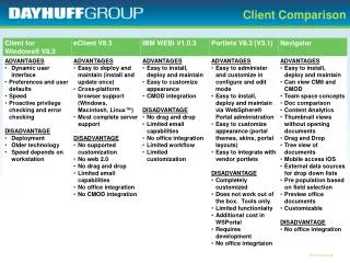
Replog Comparison. Column 5 – Device Overload N-0. Current Replog Any line, transformer or series cap bank with a loading > 100% of its listed rating Assigned to 1 st owner New Replog


Replog Comparison
E N D
Presentation Transcript
Column 5 – Device Overload N-0 • Current Replog • Any line, transformer or series cap bank with a loading > 100% of its listed rating • Assigned to 1stowner • New Replog • Same: Inconsistencies can occur between PowerWorld and GE for elements near 100% loading due to differences in element monitoring and solving methods • Assigned to 1st, 2nd, 3rd, & 4th owner • Standard • TPL-001-0.1 • “R1.3.7. Demonstrate that system performance meets Table 1 for Category A (no contingencies).” • “Category A: System Stable and Both Thermal and Voltage Limits within Applicable Rating” • “Applicable rating refers to the applicable Normal and Emergency facility thermal Rating or system voltage limit as determined and consistently applied by the system or facility owner.”
Column 6 – No Ratings • Current Replog • Missing rating in both normal seasonal rating for the case and rating A. • Assigned to 1stowner • New Replog • Same • Can be altered to check for any desired rating combination • Assigned to 1st, 2nd, 3rd, & 4th owner • DPM • Required Ratings: • Summer Normal/Emergency (Table 3: Data Requirements (AC Transmission)) • “Normal and Emergency thermal rating fields for the seasonal scenario described in the base case data request letter shall be populated for all Transformer models.”
Column 7 – Required PSS Data is Due • Current Replog • Missing Gen Stabilizer model if: • Gen is not in exemption list • Gen MVA base is >= 30 MVA • Assigned to 1stowner • New Replog • Same except gen MVA base comes from the dyd file not the base case • Assigned to 1st, 2nd, 3rd, & 4th owner • DPM • “Power System Stabilizer (PSS) Dynamic data shall be submitted for all generators that have active PSS. See the WECC Policy Statement on Power System Stabilizers document.” • WECC Policy Statement on Power System Stabilizers • “A PSS shall be installed on every existing synchronous generator that is larger than 30 MVA”
Column 8 – Data Using Non-Appv’d DYN Models • Current Replog • Generator models in the dyd file not approved by MVWG • Assigned to 1st owner • New Replog • Same • Assigned to 1st, 2nd, 3rd, & 4th owner • DPM • “All dynamic models contained in the MDF shall be those approved by MVWG. If the model you want to use is not on the approved list, you must go through MVWG and follow the WECC Dynamic Modeling Procedure.”
Column 9 – Generator Netted in DYN Data • Current Replog • Buses in the generator netted section of the dynamics file and not on the exemption list • There does not need to be a generator at the bus • Assigned to bus owner • New Replog • All closed generators without dynamics data and not on the exemption list • Assigned to 1st, 2nd, 3rd, & 4th owner of the generator • DPM • “Generation Netting: The representation of a generator(s) through the modeling a Load element with the real and reactive power requirements set to the net of generation and load. Alternatively, Generation Netting may be the representation of a generator(s) using a Load element with a negative real power demand setting. Further, Generation Netting may be used only in Dynamic simulations by including the Generator element in the Netting section of the PSLF ‘dyd’ file for a given WECC Base Case.” • “The netting of small generating units whose single capacity is greater than or equal to 10 MVA or aggregate capacity is greater than or equal to 20 MVA may not be modeled as a negative load. Generators modeled as negative load shall have an assigned load ID of ‘NT’ and have its ‘non-conforming load FLAG’ set appropriately.”
Column 10 – Generator Pgen Outside Max/Min Limits • Current Replog • Any generator generating outside of Pmax and Pmin • Assigned to 1st owner • New Replog • Same • Assigned to 1st, 2nd, 3rd, & 4th owner • Standard • TPL-001-0.1 • “R1.3.7. Demonstrate that system performance meets Table 1 for Category A (no contingencies). “ • “Category A: System Stable and Both Thermal and Voltage Limits within Applicable Rating” • “Applicable rating refers to the applicable Normal and Emergency facility thermal Rating or system voltage limit as determined and consistently applied by the system or facility owner.”
Column 12 – LSDT9 Bus Not in Powerflow • Current Replog • LSDT9 models in the dyd file that do not have a corresponding load in the case • Assigned to bus owner • New Replog • Same • Assigned to bus owner • Suggested change to assign to area • DPM • “Include pertinent load data in the MDF. All under-frequency load-shedding data in the MDF must match bus, load, and/or branch identifiers in the operating cases. For this data category, the MDF data is not a master database because it does not apply to planning cases. If data is to be included in the planning cases, the data is to be submitted with the case development and identified as planning data.”
Column 13 – Ownership No Owner • Current Replog • Generators and buses with owner number = 1 • Assigned to 1st owner • New Replog • Generators and buses with owner number = 1 or owner name/owner number = owner##/## • Buses can be added • Assigned to 1st, 2nd, 3rd, & 4th owner • DPM • “WECC staff shall assign Owner Number to required entities.”
Column 14 – Duplicate Bus Name • Current Replog • Buses with same name and nominal voltage • Buses must be in different areas • Is case sensitive • Excludes dummy buses and “mid pt” buses • Assigned to both bus owners • New Replog • Buses with same name and nominal voltage • Buses can be in same area • Not case sensitive • Excludes dummy buses and “mid pt” buses • Assigned to both bus owners • DPM • “Bus names shall be unique within the same Base Voltage class. “
Column 15 – Incorrect Zone/Area Owner • Current Replog • Elements with invalid zone • Assigned to 1st owner • New Replog • Buses with invalid zone • Other elements can be added • Assigned to bus owner • DPM • “Zones – Zone Names and Zone Numbers shall be maintained in the MTLF. Zone assignments to the applicable entities can be found in “Appendix 2 – Area, Zone, and Bus Number Assignments.””
Column 16 – LLID Missing or Incorrect • Current Replog • Loads with missing or invalid Long Load Id’s • Assigned to load owner • New Replog • Same • Assigned to load owner • DPM • “A Long ID shall be provided for each load in accordance with the WECC MVWG Load Long ID Instructions (LID_Instructions), either within the case data provided, or in a separate spreadsheet file. See Dynamic section 6B Load Characteristics. There is a separate Long ID for Station Service or generator Auxiliary loads.”