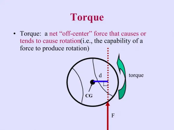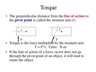
Torque on a Current Loop
Torque on a Current Loop. HW: See Schedule. Torque on a Current Loop in a Uniform Magnetic Field:. When a loop of wire carrying a current is placed in a magnetic field, the field exerts forces on the loop.

Torque on a Current Loop
E N D
Presentation Transcript
Torque on a Current Loop HW: See Schedule
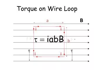
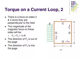
Torque on a Current Loop in a Uniform Magnetic Field: When a loop of wire carrying a current is placed in a magnetic field, the field exerts forces on the loop. Two lengths of the loop experience a force. Use right hand rule to show the directions of the forces. The two ends {front and back} are parallel to the field, so no force is made here.
This loop is at a slight angle to the field, measured as an angle between the normal vector of the area of the current loop to the magnetic field vector. The normal vector of the area of the current loop is found by curling the fingers of the right hand around the current loop in the direction of the current. The extended thumb of the right hand gives the direction of the normal vector. {figure (b)} q = angle between normal vector and field vector {figure (c)}
Note from figure (a) that the net force on the loop is zero. This is true in general for any shaped current loop placed in a uniform magnetic field. The forces along sides 2 & 4 are lie along the same line, parallel to the area of the loop. No torque is created on the loop by either of these forces. The forces along sides 1 & 3 are parallel to one another, but do not lie along the same line. These two forces produce a torque, as they are at an angle to the area of the loop
Let sides 1 & 3 have sides a and sides 2 & 4 have length b. Compute the torque about the center of the loop: Redraw picture to get specify vector directions:
The last drawings hint at a new vector that can be created: The torque equation can be written in terms of this vector: If the wire loop contains N windings (or loops), then the magnetic dipole moment equation is modified to be:
Ex. #1: Analog voltmeters and ammeters work by measuring the torque exerted by a magnetic field on a current carrying coil. The reading is displayed by means of the deflection of a pointer over a scale. The figure below shows a basic galvanometer, on which both analog ammeters and analog voltmeters are based. The coil is 2.1 cm high and 1.2 cm wide; it has 250 turns and is mounted so that it can rotate about an axis (into the page) in a uniform radial magnetic field with B = 0.23 T. For any orientation of the coil, the net magnetic field through the coil is perpendicular to the normal vector of the coil. A spring Sp provides a countertorque that balances the magnetic torque, so that a steady current I in the coil results in a steady angular deflection f. If a current of 100 mA produces an angular deflection of 28 degrees, what must be the torsional constant k of the spring?
Solution: The torque due to the magnetic interaction is balanced by the torsional spring.
Ex. #2: A length of wire L carries a current I. Show that if the wire is formed into a circular coil, the maximum torque in a given magnetic field is developed when the coil has only one turn and that the maximum torque has a magnitude Let the circular loop have N turns. The circumference and radius of the loop are: The magnetic dipole moment becomes:
The torque is given as: The maximum torque occurs when N is set equal to 1.
Ex. #3: Prove that the relation holds for closed loops of arbitrary shape and not only for rectangular loops. {Hint: Replace the loop of arbitrary shape with an assembly of adjacent long, thin, approximately rectangular loops that are nearly equivalent to the loop of arbitrary shape as far as the distribution of current is concerned.} The “proof” holds for a planar surface placed in a uniform magnetic field.
Each element of area contributes a magnetic dipole moment. Each dipole moment creates an element of torque. Sum all the contributions for the total torque. true since B is constant true since N, I, and normal unit vector are constant
Ex. #4: The figure below shows a loop ABCDEFA carrying a current i = 5.00 A. The dimensions of the loop are given in the figure. Calculate the magnetic dipole moment of this loop. Hint: Imagine equal but opposite currents in line segment AD, then treat the system as two separate loops.
Ex #5: The figure below shows a wooden cylinder with a mass m = 0.250 kg and length L = 0.100 m, with N = 10.0 turns of wire wrapped around it longitudinally, so that the plane of the wire coil contains the axis of the cylinder. What is the least current i through the coil that will prevent the cylinder from rolling down a plane inclined at an angle q to the horizontal, in the presence of a vertical, uniform magnetic field of 0.500 T, if the plane of the windings is parallel to the plane of the incline? This can be solved by balancing the torques about the contact point on the board.
clockwise torque: counterclockwise torque: