Download
1 / 40
400 likes | 426 Views
Explore fuel cell systems for efficient energy conversion. Learn about their role in renewable resources and the future hydrogen economy, focusing on classical energy carriers and the need for higher efficiencies.

E N D
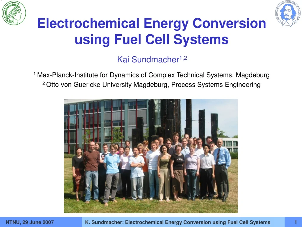
Electrochemical Energy Conversion using Fuel Cell Systems Kai Sundmacher1,2 1 Max-Planck-Institute for Dynamics of Complex Technical Systems, Magdeburg 2 Otto von Guericke University Magdeburg, Process Systems Engineering NTNU, 29 June 2007
Research Institutes at Magdeburg/Germany Fraunhofer Institute for Factory Operation and Automation Otto von Guericke University Magdeburg (11.000 students) Experimental Factory • Max Planck Institute for Dynamics of Complex • Technical Systems • 1998 started • 4 departments • ~ 200 employees Environmental Research Center (UFZ) NTNU, 29 June 2007
World Energy Demand • Strongly increasing energy demand, particularly in Asia • Dependence of many countries on limited fossile resources • economic impact: • increasing costs for energy „harvesting“ and transport • political impact:fair distribution of resources • Emissions • local: air polutionglobal: climate change Ref.: IEA (International Energy Agency) World Energy Outlook 2002 – Forecast of world energy consumption until 2020. NTNU, 29 June 2007
Solution Strategies Classical Energy Carriers Renewable Resources Need for higher efficiencies Generation Distribution Consumption • Sun • Wind • Water Flow • Geothermal • Biomass Dispersed power systems: + lower losses + combined cycles + higher net stability - net operation difficult Balancing Availability and Demand in Time and Space Intelligent energy storage and transport NTNU, 29 June 2007
Solution Strategies Classical Energy Carriers Renewable Resources Need for higher efficiencies Generation Distribution Consumption …how can Fuel Cells contribute? • Sun • Wind • Water Flow • Earth heat • Biomass Dispersed power systems: + lower losses + combined cycles + higher net stability - net operation difficult Balancing Availability and Demand in Time and Space Intelligent energy storage and transport NTNU, 29 June 2007
Solution Strategies: The Role of Fuel Cells More efficient production of electrical energy! Classical Energy Carriers Renewable Resources Need for higher efficiencies Generation Distribution Consumption • Sun • Wind • Water Flow • Earth heat • Biomass Dispersed power systems: + lower losses + combined cycles + higher net stability - net operation difficult Balancing Availability and Demand in Time and Space Intelligent energy storage and transport NTNU, 29 June 2007
Solution Strategies: The Role of Fuel Cells Classical Energy Carriers Direct conversion of primary energy at the site of consumption! Renewable Resources Need for higher efficiencies Generation Distribution Consumption • Sun • Wind • Water Flow • Earth heat • Biomass Dispersed power systems: + lower losses + combined cycles + higher net stability - net operation difficult Balancing Availability and Demand in Time and Space Intelligent energy storage and transport NTNU, 29 June 2007
Solution Strategies: The Role of Fuel Cells Classical Energy Carriers Fuel Cells ideally suited for combined cycles! Renewable Resources Need for higher efficiencies Generation Distribution Consumption • Sun • Wind • Water Flow • Earth heat • Biomass Dispersed power systems: + lower losses + combined cycles + higher net stability - net operation difficult Balancing Availability and Demand in Time and Space Intelligent energy storage and transport NTNU, 29 June 2007
Solution Strategies: The Role of Fuel Cells Classical Energy Carriers Fuel cells are key component in future hydrogen economy! Renewable Resources Need for higher efficiencies Generation Distribution Consumption • Sun • Wind • Water Flow • Earth heat • Biomass Dispersed power systems: + lower losses + combined cycles + higher net stability - net operation difficult Balancing Availability and Demand in Time and Space Intelligent energy storage and transport NTNU, 29 June 2007
Working Principle of H2-O2 Fuel Cell (PEMFC) Hydrogen Porous Cathode Porous Anode Electrolyte Polymer Electrolyte Membrane Air Catalyst Layer Gas Diffusion Layer PEM Bipolar Plate NTNU, 29 June 2007
+ - + + + + - - - - Fuel Cell Stack Stack UStack = N · Ucell • Stacking N cells in series leads to higher voltages. • Larger cross sectional area A leads to higher currents: IStack = Icell = A · icell,av A 100 mm Single Cell 100 mm Ucell = 0,5 - 0.9 V ca. 350 mm Stack by ZSW, Germany Electrical Power: 1 kW NTNU, 29 June 2007
Introduction Solid Oxide Fuel Cell: SOFC Molten Carbonate Fuel Cell: MCFC Proton Exchange Membrane Fuel Cell: PEMFC Enzymatic Fuel Cell Summary Outline 1000 °C 600 °C 80 °C 37 °C NTNU, 29 June 2007
Working Principle of MCFC Anode: Ni-10% Cr 3 – 6 mm Pores 60 % Porosity 1 mm Thickness Cathode: NiO 7 – 15 mm Pores Electrolyte Matrix: g-LiAlO2/a-Al2O3 0,5 mm Thickness Electrolyte: 62% Li2CO3 38% K2CO3 Internal Reforming (CH4) (H2) (CO) CO2 H2O O2 N2 (Air) CH4 + H2O CO+ 3H2 CO+ H2O CO2 + H2 CH4 H2O H2 + CO32- H2O + CO2 +2e- CO + CO32- 2CO2 +2e- e- Anode Catalytic Combustion Electrolyte CO32- Ucell Cathode ½O2+CO2+2e-CO32- O2 CO2 (N2) (H2O) Exchaust Air T = 580 - 650 °C NTNU, 29 June 2007
250 kW MCFC Fuel Cell Plant “HotModule” CO CO / O / O 2 2 2 2 Mixing Fan Chamber Catalytic Fresh Air Com- bustion N N / O / O 2 2 2 2 Electrical . Heater FC Stack • HotModule System being installed at • the University Hospital in Magdeburg • Molten Carbonate Fuel Cell: MCFC • 342 Cells, 250 kW Electrical Power • ca. 48% Electrical Efficiency • Feed Gas: Natural Gas • Size (L x W x H): 7,3 m x 2,5 m x 3,2 m • Mass 15 t Stainless Steal Vessel Exhaust Air Gas Distributor Feed Gas CH / H / H O O 4 4 2 2 Developed by: MTU CFC Solutions, Germany NTNU, 29 June 2007
MCFC Fuel Cell “HotModule” Fresh Air Supply 2.5 m ; 342 Cells Exhaust Air Cathode Gas Recycle Anode Effluent 1.2 m Catalytic Cathode Com- bustion Effluent 0.8 m • System Features: • 3-dimensional cell stack • Cross-flow operation • External recycles Cathode Feed Anode Feed NTNU, 29 June 2007
2D Model of MCFC Fuel Cell “HotModule” • Enthalpy and Mass Balances of Gas Phases Number Convective mass transport, hyperbolic PDE 2x7=14 PDE Convective energy transport, hyperbolic PDE 2x1=2 PDE Total mass balance, ODE in space 2x1=2 ODE • Enthalpy Balance in Solid Phase Conductive heat transport, parabolic PDE 1 PDE • Charge Balances at Electrolyte Local charge balance, ODE in time 2x1= 2 ODE Galvanostatic condition, Integral equation 1 IE 17 PDE, 4 ODE, 1 IE K. Chudej, P. Heidebrecht, V. Petzet, S. Scherdel, K. Schittkowski, H.J. Pesch, K. Sundmacher, ZAMM85 (2005) 132-140. NTNU, 29 June 2007
Anode Cathode Feed Feed CH / H O O / CO 4 2 2 2 Steady State MCFC Simulation Results Average Current Density: 125 mA/cm²; S/C = 2.5; Fuel Utilization: 70% Hydrogen at Anode P. Heidebrecht, K. Sundmacher, Journal of the Electrochemical Society 152, 2005, A2217-2228. Current Density Temperature at Cathode NTNU, 29 June 2007
Icell 0.85 0.7 step=0.1 =500 Dynamic Response to Load Change Heat Transport in Solid Parts Cell Voltage, Ucell Double Layer Charging Mass Transfer to Electrodes P. Heidebrecht, K. Sundmacher, Journal of the Electrochemical Society 152, 2005, A2217-2228. Time, t - tstep NTNU, 29 June 2007
Model-based Observer • Measurable: cell voltage, gas exit temperatures, gas exit compositions • Desirable for process control and monitoring: Information on internal temperatures and gas compositions very difficult to measure! • Solution: Observer / State Estimator ? NTNU, 29 June 2007
Model-based Observer MCFC Sensoren ? Inputs u Real Process States x Outputs y Observer Correction + - Observer Sensor Models MCFC Model NTNU, 29 June 2007
Estimation Experimental Information for Filter Validation Good Precision of State Estimation Experimental Information for Filter Correction Good Filter Convergence Model-based Observer • Experimental results: Experimental Data NTNU, 29 June 2007
Introduction Solid Oxide Fuel Cell: SOFC Molten Carbonate Fuel Cell: MCFC Proton Exchange Membrane Fuel Cell: PEMFC Enzymatic Fuel Cell Summary Outline 1000 °C 600 °C 80 °C 37 °C NTNU, 29 June 2007
SOFC: Candidate for Steady State Power Plants DC/AC Converter SOFC:Solid Oxide Fuel Cell Electrolyte: Solid Oxide Ceramics (YSZ) Effectiveness: 55 – 65 % Temperature: 800 - 1000 °C Future Use: Power plants for kW - GW range USV Gas Feed Electrical Switches Anode Solid Oxide Cathode Cathode Contactors Electrolyte Cathode Fuel Gas Source: Siemens-Westinghouse, www.powergeneration.siemens.com/en/fuelcells Air Anode NTNU, 29 June 2007
Metallic Conductor Charge transport by electrons Electrical conductivity decreases at increasing temperature If local temperature increases: local current density decreases local heat production decreases (Ohmic losses) self-stabilizing effect Oxygen Ion Conductor (Fuel Cell) Charge transport by ions Electrical conductivity increases at increasing temperature If local temperature increases: local current density increases local heat production increases (Ohmic losses + reaction heat) de-stabilizing effect Temperature Effects in Electrical Conductors - + current density current density + - Mangold, M., Krasnyk, K., Sundmacher, K., Chemical Engineering Science 59 (2004) 4869 - 4877 NTNU, 29 June 2007
Model asumptions: 1D approach (gradients only in y-direction) Heat transport via heat conduction (Fourier’s law) Concentration polarization neglected Infinitely high electrical conductivity of electrodes Arrhenius-type temperature dependence of electrical conductivity Simple 1D Model for SOFC Mangold, M., Krasnyk, K., Sundmacher, K., Chemical Engineering Science 59 (2004) 4869 - 4877 NTNU, 29 June 2007
SOFC: Dimensionsless Model Equations • Energy balance: • Boundary conditions: • Electrochemical kinetics at anode and cathode: • Ohm’s law for ion transport in electrolyte: Arrhenius term • Overall charge balance for electrodes: NTNU, 29 June 2007
Solutions for a fuel cell of infinite length: SOFC: Phase Portrait at Ucell = const. • Periodic solutions along space coordinate possible! NTNU, 29 June 2007
Solutions for a fuel cell of finite length: left boundary: right boundary: SOFC: Phase Portrait at Ucell = const. NTNU, 29 June 2007
gE1 gE1 gE2> gE2 gE3> SOFC: Current Instabilities at Icell = const. Mangold, M., Krasnyk, K., Sundmacher, K., Chemical Engineering Science 59 (2004) 4869 - 4877 NTNU, 29 June 2007
Introduction Solid Oxide Fuel Cell: SOFC Molten Carbonate Fuel Cell: MCFC Proton Exchange Membrane Fuel Cell: PEMFC Enzymatic Fuel Cell Summary Outline 1000 °C 600 °C 80 °C 37 °C NTNU, 29 June 2007
PEMFC: Use in Mobile Applications PEMFC: Polymer Electrolyte Membrane Fuel Cell Electrolyte: Polymeric Membrane as Ion Conductor Efficiency: 30 - 50% Temperature: 20 - 100 °C (Goal: 180 °C) Use: Cars, portable devices, battery substitute H2 Anode PEM Cathode H+ e- H2O O2 Problem: Membrane Water Management Opel HydroGen 3 (2001) H2-operation, 150 km/h, 400 km distance Source: Adam Opel AG NTNU, 29 June 2007
Map of Operating Modi Gas Humidity Hydrogen Feed Flow Hanke, Mangold, KS, Fuel Cells 5 (2005) 133 Hanke-Rauschenbach, Mangold, KS, JPS (2006) in prep. PEMFC: Multiple Steady Operating States H2 + ½ O2 H2O PEM Fuel Cell: Water production curve: s Water removal line: Water activity in membrane, aH2O NTNU, 29 June 2007
Response behaviour at load variations PEMFC: Nonlinear Operating Dynamics Current Voltage Curve Humidity reduction R. Hanke-Rauschenbach, M. Mangold, K. Sundmacher, JPS (2006) in prep. R. Hanke-Rauschenbach, M. Mangold, K. Sundmacher, AIChE Meeting, San Francisco, 12-17 Nov. 2006. NTNU, 29 June 2007
Introduction Solid Oxide Fuel Cell: SOFC Molten Carbonate Fuel Cell: MCFC Proton Exchange Membrane Fuel Cell: PEMFC Enzymatic Fuel Cell Summary Outline 1000 °C 600 °C 80 °C 37 °C NTNU, 29 June 2007
Hearing Devices Pacemakers Neuro-Stimulators LVAD Artificial Hearts ICD/CHF Devices Insulin Pumps Drug Pumps Incontinence Devices Bone Growth Stimulators Enzymatic Fuel Cells: Possible Biomedical Applications Goal: Implantable fuel cell in the mW to W range NTNU, 29 June 2007
FAD Glucose Oxidase, GOX Redox Processes in Biology Oxidation FAD = Flavin Adenin Dinucleotid is a redox cofactor of the enzyme Glucose Oxidase Reduction NTNU, 29 June 2007
Anode: C6H12O6 C6H10O6 + 2e- + 2H+ Oxidation E = - 0.5 V Cathode: ½ O2 + 2e- + 2H+ H2OReduction E = 0.7 V Overall: C6H12O6 + ½ O2 C6H10O6 + H2O ΔE = 1.2 V Enzymatic Fuel Cell: Working Principle ANODE e- Voltage H2O Anode Cathode gluconic acid Immobilisation H+ e- enzymes e- redox center O2 Electron transfer Current ~ Enzymes per Area glucose NTNU, 29 June 2007
apo-GOX Immobilisation of Glucose Oxidase at Gold Electrode PQQ = Mediator: redox-active component for electron transfer between enzyme and electrode EDC, NHS EDC, NHS Au glucose e- e- gluconic acid NTNU, 29 June 2007
apo-GOX Enzyme Electrode: Proof of Principle with Glucose e- glucose gluconic acid e- Onset potential Thermodynamic potential Overpotential NTNU, 29 June 2007
Summary: Important Trends in Fuel Cell Engineering • High temperature fuel cells: • Molten Carbonate fuel cells (HotModule) are very close to the market • Efficient co-production of electricity and heat • Internal direct reforming (DIR) is most attractive process variant • Low temperature fuel cells: • PEMFC: Problem of water management in membranes • Development of water-free membranes for mobile applications • Enzymatic fuel cells: • Biomedical applications: interdisciplinary collaboration between chemical engineering, electrochemistry and organic chemistry necessary NTNU, 29 June 2007