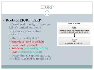
Configuring and Verifying EIGRP for Enterprise WAN with Frame Relay
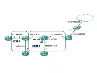
This document covers the configuration and verification of EIGRP (Enhanced Interior Gateway Routing Protocol) within an enterprise WAN architecture using Frame Relay technology. It discusses the concepts of Non-Broadcast Multi-Access (NBMA) networks, neighbor discovery through static and dynamic mappings, and the various topologies including full mesh, partial mesh, and hub-and-spoke arrangements. You'll learn how to implement dynamic and static mappings, manage EIGRP neighbor relationships, and understand the nuances of multipoint and point-to-point subinterfaces under Frame Relay.

Configuring and Verifying EIGRP for Enterprise WAN with Frame Relay
E N D
Presentation Transcript
Configuring and Verifying EIGRP for the Enterprise WAN Architecture Implementing an EIGRP-Based Solution
Frame Relay Overview • Frame Relay network • NBMA = nonbroadcast multiaccess network • Pseudo-broadcasting • Requires mapping from Layer 3 to Layer 2 (IP-to-DLCI) • Static mapping • Dynamic mapping • Neighbor loss detected only after the hold time expires or the interface goes down • Different topologies • Full mesh • Partial mesh • Hub and spoke
EIGRP with Dynamic Mapping • A single IP subnet is used • Inverse ARP is enabled by default • Split horizon is disabled on the physical interface by default R1# interface Serial0/0 encapsulation frame-relay ip address 192.168.1.101 255.255.255.0 ! router eigrp 110 network 172.16.1.0 0.0.0.255 network 192.168.1.0
R1#show ip eigrp neighbors IP-EIGRP neighbors for process 110 H Address Interface Hold Uptime SRTT RTO Q Seq (sec) (ms) Cnt Num 0 192.168.1.102 Se0/0 10 00:07:22 10 2280 0 5 1 192.168.1.103 Se0/0 10 00:09:34 10 2320 0 9 R3#show ip eigrp neighbors IP-EIGRP neighbors for process 110 H Address Interface Hold Uptime SRTT RTO Q Seq (sec) (ms) Cnt Num 0 192.168.1.101 Se0/0 10 00:11:45 10 1910 0 6 1 192.168.1.102 Se0/0 10 00:02:11 10 2210 0 3 EIGRP with Dynamic Mapping (Cont.)
EIGRP with Static Mapping • A single IP subnet is used • Split horizon is disabled on the physical interface by default • Inverse ARP is not used R1(config)# interface Serial0/0 encapsulation frame-relay ip address 192.168.1.101 255.255.255.0 frame-relay map ip 192.168.1.101 101 frame-relay map ip 192.168.1.102 102 broadcast frame-relay map ip 192.168.1.103 103 broadcast ! router eigrp 110 network 172.16.1.0 0.0.0.255 network 192.168.1.0
R1#show ip eigrp neighbors IP-EIGRP neighbors for process 110 H Address Interface Hold Uptime SRTT RTO Q Seq (sec) (ms) Cnt Num 0 192.168.1.102 Se0/0 10 00:06:20 10 2280 0 5 1 192.168.1.103 Se0/0 10 00:08:31 10 2320 0 9 R3#show ip eigrp neighbors IP-EIGRP neighbors for process 110 H Address Interface Hold Uptime SRTT RTO Q Seq (sec) (ms) Cnt Num 0 192.168.1.101 Se0/0 10 00:10:44 10 1910 0 6 1 192.168.1.102 Se0/0 10 00:03:02 10 2210 0 3 EIGRP with Static Mapping (Cont.)
Frame Relay Multipoint Subinterfaces • Several multipoint subinterfaces can be created: • Logical interfaces emulating the multiaccess network • Like NBMA physical interfaces for routing purposes • IP address space may be saved, since a single subnet is used. • Subinterfaces are applicable to partial-mesh and full-mesh topologies. • Neighbor loss is detected only after the hold time expires or the subinterface goes down.
EIGRP over Multipoint Subinterfaces • A single IP subnet is used. • Mapping is applied to the subinterface. • Splithorizon must be disabled in partial-mesh topologies. R1# interface Serial0/0 no ip address encapsulation frame-relay no frame-relay inverse-arp eigrp 110 ! interface Serial0/0.1 multipoint ip address 192.168.1.101 255.255.255.0 no ip split-horizon eigrp 110 frame-relay map ip 192.168.1.101 101 frame-relay map ip 192.168.1.102 102 broadcast frame-relay map ip 192.168.1.103 103 broadcast ! router eigrp 110 network 172.16.1.0 0.0.0.255 network 192.168.1.0
R1#show ip eigrp neighbors IP-EIGRP neighbors for process 110 H Address Interface Hold Uptime SRTT RTO Q Seq (sec) (ms) Cnt Num 0 192.168.1.102 Se0/0.1 10 00:06:41 10 2280 0 5 1 192.168.1.103 Se0/0.1 10 00:08:52 10 2320 0 9 R3#show ip eigrp neighbors IP-EIGRP neighbors for process 110 H Address Interface Hold Uptime SRTT RTO Q Seq (sec) (ms) Cnt Num 0 192.168.1.101 Se0/0.1 10 00:10:37 10 1910 0 6 1 192.168.1.102 Se0/0.1 10 00:03:12 10 2210 0 3 EIGRP over Multipoint Subinterfaces (Cont.)
EIGRP Unicast Neighbor • Settinga neighbor with the command to enable a unicast neighbor relationship R1# interface FastEthernet0/0 ip address 172.16.1.1 255.255.255.0 ! interface Serial0/0.1 multipoint ip address 192.168.1.101 255.255.255.0 frame-relay map ip 192.168.1.102 102 broadcast frame-relay map ip 192.168.1.103 103 broadcast ! router eigrp 110 network 172.16.1.0 0.0.0.255 network 192.168.1.0 neighbor 192.168.1.102
EIGRP Unicast Neighbor (cont.) R2# interface FastEthernet0/0 ip address 172.17.2.2 255.255.255.0 ! interface Serial0/0.1 multipoint ip address 192.168.1.102 255.255.255.0 frame-relay map ip 192.168.1.101 102 broadcast ! router eigrp 110 network 172.17.2.0 0.0.0.255 network 192.168.1.0 neighbor 192.168.1.101
R1#show ip eigrp neighbors IP-EIGRP neighbors for process 110 H Address Interface Hold Uptime SRTT RTO Q Seq (sec) (ms) Cnt Num 0 192.168.1.102 Se0/0/1 10 00:07:22 10 2280 0 5 R2#show ip eigrp neighbors IP-EIGRP neighbors for process 110 H Address Interface Hold Uptime SRTT RTO Q Seq (sec) (ms) Cnt Num 0 192.168.1.101 Se0/0/1 10 00:17:02 10 1380 0 5 Verifying EIGRP Unicast Neighbors
Frame Relay Point-to-Point Subinterfaces • Several point-to-point subinterfaces can be created: • Logical interfaces emulating a leased-line network • Like physical point-to-point interfaces for routing purposes • Each point-to-point subinterface requires its own subnet. • Applicable to hub-and-spoke topologies. • Neighbor loss is detected after the hold time expires, the subinterface goes down, or the DLCI is lost.
EIGRP over Point-to-Point Subinterfaces R1# interface Serial0/0 no ip address encapsulation frame-relay ! interface Serial0/0.2 point-to-point ip address 192.168.2.101 255.255.255.0 frame-relay interface-dlci 102 ! interface Serial0/0.3 point-to-point ip address 192.168.3.101 255.255.255.0 frame-relay interface-dlci 103 ! router eigrp 110 network 172.16.1.0 0.0.0.255 network 192.168.2.0 network 192.168.3.0 R3# interface Serial0/0 no ip address encapsulation frame-relay ! interface Serial0/0.1 point-to-point ip address 192.168.3.103 255.255.255.0 frame-relay interface-dlci 103 ! router eigrp 110 network 172.16.3.0 0.0.0.255 network 192.168.3.0
R1#show ip eigrp neighbors IP-EIGRP neighbors for process 110 H Address Interface Hold Uptime SRTT RTO Q Seq (sec) (ms) Cnt Num 0 192.168.2.102 Se0/0.2 10 00:08:04 10 2280 0 5 1 192.168.3.103 Se0/0.3 10 00:10:12 10 2320 0 9 R3#show ip eigrp neighbors IP-EIGRP neighbors for process 110 H Address Interface Hold Uptime SRTT RTO Q Seq (sec) (ms) Cnt Num 0 192.168.3.101 Se0/0.1 10 00:13:25 10 1910 0 6 EIGRP over Point-to-Point Subinterfaces (Cont.)
EIGRP Load Balancing • Routes with a metric equal to the minimum metric are installed in the routing table - equal-metric load balancing • Up to 16 entries can be in the routing table for the same destination (default is 4) • Maximum number is configurable • To disable load balancing, set the value to one • To control the maximum number of parallel routes that an IP routing protocol can support R1(config)# router eigrp 110 maximum–paths 2
R1#show ip route eigrp <output omitted> 172.16.0.0/16 is variably subnetted, 2 subnets, 2 masks D 172.16.2.0/24 [90/2809856] via 192.168.1.2, 00:07:01, Serial1/1 [90/2809856] via 192.168.2.2, 00:07:01, Serial1/2 [90/2809856] via 192.168.3.2, 00:07:01, Serial1/3 <output omitted> EIGRP Load Balancing (Cont.) R1# router eigrp 110 network 172.16.1.0 0.0.0.255 network 192.168.1.0 network 192.168.2.0 network 192.168.3.0 network 192.168.4.0 maximum–paths 3
EIGRP Unequal-Cost Load Balancing • The router can balance traffic across multiple routes that have different metrics to a destination • Successor is always used • Feasible successors are used if the cost is less than (minimum cost * variance) • Variance is only a multiplier, not a max-path parameter • The maximum number of paths is limited by the maximum–paths command • Variance opens the gate for unequal-cost load balancing • To control load balancing in an internetwork based on EIGRP R1(config)# router eigrp 110 variance 2
R1#show ip route eigrp <output omitted> 172.16.0.0/16 is variably subnetted, 2 subnets, 2 masks D 172.16.2.0/24 [90/10665472] via 192.168.2.2, 00:07:01, Serial1/2 [90/11151872] via 192.168.1.2, 00:07:01, Serial1/1 <output omitted> EIGRP Unequal-Cost Load Balancing (Cont.) R1# router eigrp 110 variance 2 R1 EIGRP Topology for 172.16.2.0 - AD(R4)>FD(R3) - Variance: 50(FD)>2*20(FD,Successor)
EIGRP Bandwidth Utilization over WAN • Up to 50% of bandwidth is utilized by default and can be changed • Point-to-point interfaces • Treat bandwidth as T1 by default • Configure bandwidth manually • Multipoint interfaces • Bandwidth on the physical interface divided by the number of neighbors on that interface • To configure the percentage of bandwidth that may be used by EIGRP on an interface R1(config-if)# bandwidth 256 ip bandwidth-percent eigrp 110 80
Bandwidth Utilization Issues • Each PVC can have a different CIR, creating an EIGRP packet-pacing problem. • Multipoint interfaces: • Convert to point-to-point configuration OR • Manually configure bandwidth by multiplying the lowest CIR by the number of PVCs.
EIGRP Hub-and-Spoke WAN Utilization • Configure each VC as point-to-point—do not change number of VCs to preserve the configuration • Set bandwidth to 1/10 of link capacity • Increase EIGRP utilization to 50% of actual VC capacity R1# interface serial0 bandwidth 256 interface serial0.1 point-to-point ip bandwidth-percent eigrp 110 128 <output omitted> interface serial0.10 point-to-point ip bandwidth-percent eigrp 110 128 R5# interface serial0 bandwidth 25 ip bandwidth-percent eigrp 110 128
EIGRP Multipoint WAN Utilization • Solution 1: create on multipoint interfaces • (Lowest CIR * number of VCs) = (56 kb/s * 4) = 224 kb/s R1(config)# interface serial0 bandwidth 224
EIGRP Hybrid Multipoint WAN Utilization (Cont.) • Solution 2: create separate multipoint interfaces • Configure the lowest CIR VC as point-to-point and set bandwidth = CIR. • Configure higher CIR VCs as multipoint, combine CIRs, and configure the sum of bandwidth to the subinterface. R1# interface serial0.1 multipoint bandwidth 768 ! interface serial0.2 point-to-point bandwidth 56
AToM Overview • Service providers offer Layer 2 transport services to connect customer equipment (CE) • Ethernet, Ethernet VLAN • ATM • PPP, HLDC, and so on • Any Transport Over MPLS • Enables the sending of Layer 2 frames across the MPLS backbone • Unifies Layer 2 and Layer 3 over a common MPLS infrastructure • Virtual circuits represent Layer 2 links • Labels identify virtual circuits
Layer 2 MPLS VPN backbone solution Layer 3 MPLS VPN backbone solution Layer 2 and Layer 3 MPLS VPN Solutions
Layer 3 MPLS VPN Overview • Service provider is connecting multiple customers over a common MPLS backbone using MPLS VPNs • Customer Edge (CE) devices connect into the service provider MPLS VPN network
Customer MPLS Perspective • CE routers run EIGRP and exchange routing updates with the PE router • The PE router appears as another router in the customer’s network • The service provider’s P-routers are hidden from the customer • CE-routers are unaware of MPLS VPN • EIGRP parameters must be agreed upon with service provider
Ethernet Port-to-Port Connectivity • Customer routers R1 and R2 exchange Ethernet frames • Frame propagation occurs across the MPLS transport network • Ethernet frames: from R1 to PE1 and from PE2 to router R2 • MPLS packet: Between PE1 and PE2 • EoMPLS service does participate in Spanning Tree Protocol nor learns MAC addresses
Ethernet VLAN Connectivity • Customer routers R1 and R2 exchange Ethernet frames via VLAN subinterfaces • Frame propagation occurs across the MPLS transport network • Ethernet frames: from R1 to PE1 and from PE2 to router R2 • MPLS packet: Between PE1 and PE2 • EoMPLS service does participate in Spanning Tree Protocol nor learns MAC addresses
R1#show ip eigrp neighbors IP-EIGRP neighbors for process 110 H Address Interface Hold Uptime SRTT RTO Q Seq (sec) (ms) Cnt Num 0 192.168.1.102 Fe0/0 10 00:07:22 10 2280 0 5 R2#show ip eigrp neighbors IP-EIGRP neighbors for process 110 H Address Interface Hold Uptime SRTT RTO Q Seq (sec) (ms) Cnt Num 0 192.168.1.101 Fe0/0 10 00:17:02 10 1380 0 5 EIGRP over EoMPLS R1# interface FastEthernet0/0 ip address 192.168.1.101 255.255.255.224 ! router eigrp 110 network 172.16.1.0 0.0.0.255 network 192.168.1.0 R2# interface FastEthernet0/0 ip address 192.168.1.102 255.255.255.224 ! router eigrp 110 network 172.17.2.0 0.0.0.255 network 192.168.1.0
R1#show ip eigrp neighbors IP-EIGRP neighbors for process 110 H Address Interface Hold Uptime SRTT RTO Q Seq (sec) (ms) Cnt Num 0 192.168.1.1 Fe0/0 10 00:07:22 10 2280 0 5 R2#show ip eigrp neighbors IP-EIGRP neighbors for process 110 H Address Interface Hold Uptime SRTT RTO Q Seq (sec) (ms) Cnt Num 0 192.168.2.2 Fe0/0 10 00:17:02 10 1380 0 5 EIGRP over Layer 3 MPLS VPN R1# interface FastEthernet0/0 ip address 192.168.1.2 255.255.255.252 ! router eigrp 110 network 172.16.1.0 0.0.0.255 network 192.168.1.0 R2# interface FastEthernet0/0 ip address 192.168.2.2 255.255.255.252 ! router eigrp 110 network 172.17.2.0 0.0.0.255 network 192.168.2.0
Summary • When EIGRP is deployed over a Frame Relay physical interface, neighbor loss is detected after the hold time expires or all DLCIs are down. • EIGRP routing behavior over Frame Relay multipoint interfaces is equivalent to NBMA physical interfaces. • When EIGRP is deployed over a Frame Relay point-to-point interface, neighbor loss is detected after the hold time expires or the interface DLCI goes down • EIGRP performs equal-cost load balancing by default for up to four paths (up to six paths can be supported).
Summary (Cont.) • To support unequal-cost load balancing, a multiplier parameter (variance) should be configured. • EIGRP uses up to 50% of the bandwidth of an interface by default. This may not be the best option for all WAN links, due to the inherent differences in the operational characteristics of WANs. • CE-routers connected to a service provider’s EoMPLS (Layer 2 MPLS VPN) treat the connection as a separate subnet. Therefore, EIGRP operates normally without changes in the basic configuration. • A customer connected to a Layer 3 MPLS VPN must agree with its service provider on EIGRP parameters (AS number, authentication, and so on) in order to deploy routing.