Introduction to Designing Elastomeric Vibration Isolators
290 likes | 508 Views
Introduction to Designing Elastomeric Vibration Isolators. Christopher Hopkins OPTI 512 08 DEC 2009. Introduction. Why elastomers? Key design parameters Loading Configuration Spring rates Design considerations Steps to designing a simple isolator. Elastomers.

Introduction to Designing Elastomeric Vibration Isolators
E N D
Presentation Transcript
Introduction to Designing Elastomeric Vibration Isolators Christopher Hopkins OPTI 512 08 DEC 2009
Introduction • Why elastomers? • Key design parameters • Loading • Configuration • Spring rates • Design considerations • Steps to designing a simple isolator
Elastomers • An eastomer is any elastic polymer • Silicone Rubber • Butyl Rubber • Fluorosilicone Rubber • Material selection dependent on application • Ulitimate Loading • Sensitivity to Environment • Internal Properties
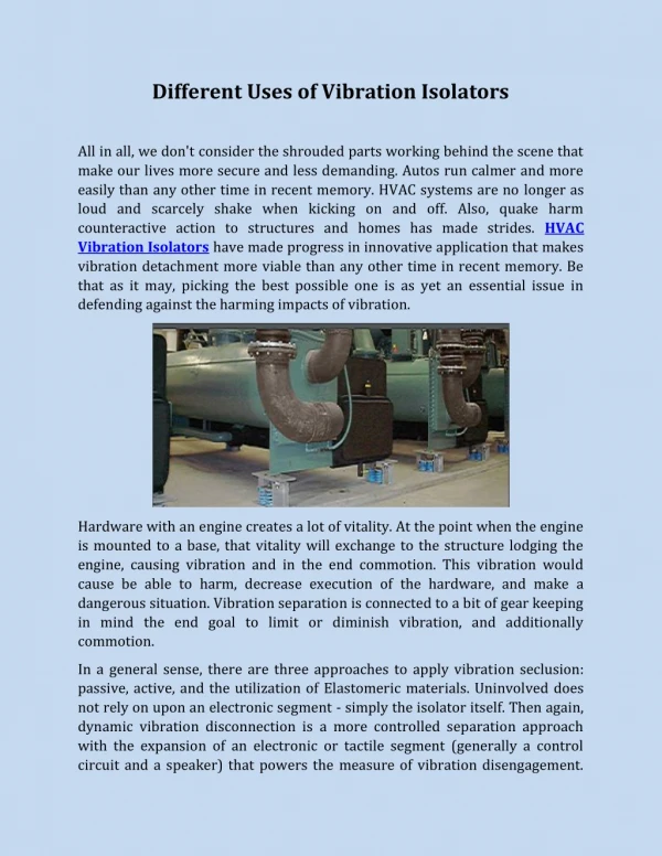
Elastomeric Isolators • Engineered properties can meet specific applications • Modulus of elasticity • Internal dampening • Homogeneous nature allows for compact forms • Easily manufactured • Molded • Formed in place
Key Isolator Design Parameters • Configuration • Loading • Spring rate • Shear, Bulk, and Young’s modulus • Geometry • Ultimate strength • Internal dampening • Maximum displacement
Simple Isolator Configurations • Planer Sandwich Form • Laminate • Cylindrical
Spring Rates • Isolator spring rate sets system resonant frequency • Ratio of resonant frequency to input frequency plus dampening control amount of isolation • For an elastomer, spring rate is determined by • Shape factor • Loading: shear, compression, tension • Material Properties: bulk, shear, and young’s modulus
Shape Factor • Ratio of load area to bulge area • Easy to calculate for simple shapes simply loaded • Planer sandwich forms are simple • Tube form bearings are more difficult, but can be approximated as a planer form
Shear Spring Rate • Design isolator to attenuate in shear if possible • Dependent on load area, thickness, and shear modulus • Shear modulus is linear up to 75%-100% strain • Shear modulus for large shape factors is also effected by high compressive loads • When aspect ratio exceeds 0.25 a correction factor is added to account for bending
Compression Spring Rate • Designed properly, compression can provide high stiffness • Depends on load area, effective compression modulus, and thickness • Effective compression modulus • Linear up to 30% strain • Can be tricky to compute
Tension Spring Rate • Try to avoid having elastomeric isolators in tension • Low modulus • Can be damaged by relatively low loads • Apply preload avoids this • Easy to do for cylindrical isolators • Must include correction to shape factor
Finding Modulus • Many elastomers are listed with only with • Durometer Shore hardness • Ultimate strength (MPa or psi) • Contacting manufacturer may be useful • Perform tests • Shear stress is 1/3 Young’s modulus as poisson’s ratio approaches 0.5 • Use Gent’s relation between Shore A hardness and Young’s modulus (if you gotta have it now)
Effective Compression Modulus, Ec • Dependent on shape factor, young’s modulus and bulk modulus • Also know as the apparent compressive modulus • As Poisson’s ratio approaches 0.5, Ec may be separated into three zones depending on shape factor • For large shape factors: Ec ≈ bulk modulus • For small shape factors: Ec ≈ young’s modulus • Transisiton zone for intermediate shape factors
Computing Ec • Gent provides a reference graph • Hatheway found empirically that the transition zone is (Ec/E)∙(t/D)1.583=0.3660 • Can calculate Ec or the simple case of a circular load area of diameter D and thickness t • Find the break points • First break point: (t/D)1.583 = 0.366∙(E/EB) • Second break point: (t/D)1.583 = 0.366
Laminate Isolator • Shear modulus is not effected by shape factor (if aspect ratio is <0.25) • Effective compression modulus strongly influence by shape factor • Possible to design an isolator that is very stiff in compression and compliant in shear
Cylindrical Isolator • Shear • Axial loading • Torsion • Compression • Radial loading • Shape factor calculation for compression
Design Considerations • What is being Isolated? • What are the inputs? • Are there static loads? • What are the environmental conditions? • What is the allowable system response? • What is the service life?
Example Design Process for a Simple Isolator • Single excitation frequency • Circular cross section, planar geometery • All other components infinitely rigid • Low dampening • Attenuation provided in shear
Design Process • Specifications • Mass, input vibration, required attenuation, max displacement • Use transmissibility to determine resonance frequency and spring rate • Find isolator minimum area (A) • Total number of isolators and max allowable stress • Select modulus (G)
Design Process (con’t) • Knowing area (A), modulus (G), and spring rate (ks), calculate thickness (t) • Calculate radius, verify aspect ratio < 0.25 to avoid bending effect • Find static deflection • Is static plus dynamic deflection < max allowable deflection? • Find static shear strain • Low strain reduces fatigue (<20%)
Conclusion • Careful selection of parameters necessary to use methods presented. Can get complicated quick • Low strains • Low loads • Try to stay clear of the transition zone between Young’s and the bulk modulus • For multiple input frequencies, need to consider if dampening (η) is necessary • May need to include considerations other than just isolation • Stresses due to CTE mismatch
References • P. M. Sheridan, F. O. James, and T. S. Miller, “Design of components,” in Engineering with Rubber (A. N. Gent, ed.), pp. 209{Munich:Hanser, 1992) • A. E. Hatheway, “Designing Elastomeric Mirror Mountings,”Proc. of SPIE Vol. 6665 (2007) • Daniel Vukobratovich and Suzanne M. Vukobratovich “Introduction to Opto‐mechanical design” • A. N. Gent, “On The Relation Between Indentation Hardness and Young’s Modulus,” IRI Trans. Vol. 34, pg.46-57 (1958)