Download
1 / 31
310 likes | 335 Views
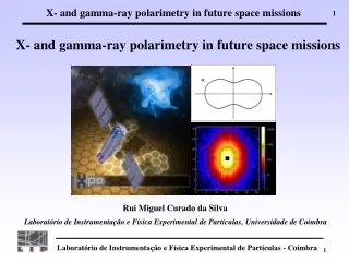
X- and gamma-ray polarimetry in future space missions. Rui Miguel Curado da Silva. Laboratório de Instrumentação e Física Experimental de Partículas, Universidade de Coimbra. Klein-Nishina cross-section for linearly polarized photons:. 90º symmetry. . Polarization direction. .

E N D
X- and gamma-ray polarimetry in future space missions Rui Miguel Curado da Silva Laboratório de Instrumentação e Física Experimental de Partículas, Universidade de Coimbra
Klein-Nishina cross-section for linearly polarized photons: 90º symmetry Polarization direction Q factor (°) Compton Polarimetry
100 % Polarised photons Energy range: 100 keV to 1 MeV 2002 j - angle between incident photon polarisation direction and the scattering plane. 128 128 CZT Pixel Matrix
100 keV 200 keV 300 keV 400 keV 500 keV 600 keV 700 keV 800 keV 900 keV 1 MeV Polarization direction Double interactions
Crab Balloon Satellite Minimum Detectable Polarisation
POLCA: POLarisation with CdTe Array European Synchrotron Radiation Facility Synchrotron ~ 99 % polarized radiation Beam line (ID15)
4x4 Monolithic CdTe Matrix Preamplifiers CdTe prototype tested at the ESRF under a 100% polarized beam
Q factor comparison: experiment vs simulations POLCA experiment Monte Carlo
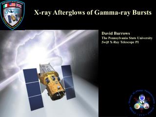
The Gamma-Ray Imager Mission for ESA Cosmic Vision Laue Lens Focal Plane
Laue Lens Development CLAIRE Ge crystal lens (integration) (courtesy: P. von Ballmoos) Cu crystal monochromator (courtesy: ILL) Lens requirements: Mounting and control of several 10 000 crystal is a technological challenge R&D work underway: CESR, Toulouse, France and Physics Department, University of Ferrara, Italy
Laue Lens Point Spread Function on the Focal Plane On Axis Laue Lens PSF @ 300 keV Off Axis (2’) Laue Lens PSF @ 300 keV
Experimental Setup of POLCA II • 150 keV to 750 keV energy range • ~ 99% polarised beam • 75 cm between crystals and detector
Polarized Gamma-rays after Laue Diffraction For the first time polarized gamma-rays were observed after Laue crystal diffraction. (De Chiara and F. Frontera, Applied Optics, Vol. 31, 1992 and “Theory of X-ray Diffraction in Crystals”, Zachariasen, Dover Publications, 1994) Diffracted Beam Direct Beam
LaPOLCA The transmitted beam was left outside the sensitive area of the detector, except 345 keV for which the diffraction angle was too small. For each energy (90, 270 and 345 keV) =>16 measurements (3 laue lens rings) Simulation of a Laue lens ring: 1st step: rotation of the Cu crystal by step of 22.5⁰ 2nd step: move the detector to get the diffracted beam on Pixel 201 centre .
XIPE The X-ray Imaging Polarimetry Explorer PI: Enrico Costa, INAF/IAPS Photoelectric effect polarimetry Submitted July 15th 2012 to ESA Call for Small Mission opportunity (launch in 2017)
EXP: Efficient X-ray Photoelectric Polarimeters, MESP:Medium Energy Solar Polarimeter
2D–Micro-Hole & Strip Plate • Double-sided microstructure: • Perforated pattern of a GEM • Microstrip pattern (bottom)
5.22 keV polarized X-rays 7.84 keV polarized X-rays
Next Challenges 1-XIPE: ESA proposal evaluation by October 2012. 2-CIPHER (Coded Imager and Polarimeter for High Energy Radiation): A wide field coded mask balloon borne telescope based on a 3D spatial resolution CdZnTe detector operating in the energy band between 100 keV and 10 MeV. PI: Ezio Caroli, IASF Bologna, Italy. Partner countries: Denmark, France, Italy, Portugal and Spain. 3- Next ESA call for M class missions (2014?) Presenting an updated Laue lens gamma-ray telescope with reformulated DUAL consortium. 4- Fermi satellite polarization data analysis Top Secret (shhh!...).
Polarisation direction 150 keV 250 keV Polarisation direction 450 keV 550 keV Double Event Maps Correction Method: Compton polarimetry 90º symmetry => extrapolation from 11×11 to a 21×21
Double event distributions (90º symmetry) 7.5 mm 300 keV 400 keV Polarisation direction Beam Beam
POLCA II Prototype • Detector + Electronics • 40x40 mm2 CZT detector • 2.5x2.5 mm2 pixel • 5 mm thick • 16x16 pixels (active: 11x11) • ASIC readout electronics • Coincidence for double and multiple event detection • POLCA II Work Plan • Laue Lens crystal response analysed by a CZT matrix detector • Polarimetric response on the range 100 keV - 650 keV • Q factor vs the angle between polarisation vector and detector axis • Analog Front-End Electronics: • eV products 16 channels ASIC • Programmable peaking time and gain • Energy threshold (CZT): <20 keV • Power: ~10 mW/ch
45º Polarization Angle Q vs Radial Bin