Download
1 / 27
280 likes | 448 Views
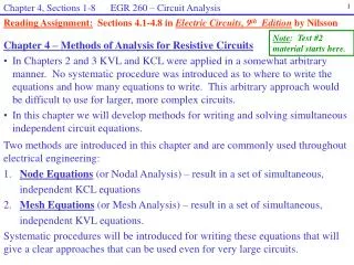
Chapter 3 EGR 260 – Circuit Analysis. 1. Reading Assignment: Chapter 3 in Electric Circuits, 9 th Edition by Nilsson. Chapter 3: Analysis of simple resistive circuits Series Resistance

E N D
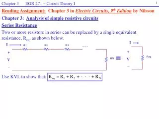
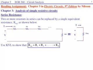
Chapter 3 EGR 260 – Circuit Analysis 1 Reading Assignment: Chapter 3 in Electric Circuits, 9th Edition by Nilsson Chapter 3: Analysis of simple resistive circuits Series Resistance Two or more resistors in series can be replaced by a single equivalent resistance, Req, as shown below. I I . . . + + V V _ _ Use KVL to show that:
Chapter 3 EGR 260 – Circuit Analysis 2 I 3 5 8V 6V 15V 2 7 4 20V Example: Determine the current I in the circuit shown below.
Chapter 3 EGR 260 – Circuit Analysis 3 I I . . . + + V V _ _ . . . Parallel Resistance Two or more resistors in parallel can be replaced by a single equivalent resistance, Req, as shown below. Use KCL to show that:
Chapter 3 EGR 260 – Circuit Analysis 4 + V 3A 120 60 7A 80 240 8A _ Example: Find the equivalent resistance for the circuit shown below. Example: Find the voltage V in the circuit shown below.
Chapter 3 EGR 260 – Circuit Analysis 5 Special Case - 2 Resistors in Parallel An easy formula can be used to calculate the equivalent of two resistors in parallel. Show that the general formula for parallel resistance can be simplified as follows: (For 2 resistors only) (For 2 or more resistors)
Chapter 3 EGR 260 – Circuit Analysis 6 Example: Find the equivalent resistance in each case using the formula for two resistors only. • Equal Value Resistors • Show the result of two equal value resistors in parallel. • Show the result of N equal value resistors in parallel.
Chapter 3 EGR 260 – Circuit Analysis 7 I Series/Parallel Combination of Resistors Circuits can sometimes be reduced through repeated series or parallel combinations of resistors. Example: Find the current I in the circuit shown below.
Chapter 3 EGR 260 – Circuit Analysis 8 • Two useful tools for analyzing resistive circuits • Voltage Division (or the Voltage Divider Law) • Current Division (or the Current Divider Law) • Voltage Division • Applies to series circuits only. • Voltage divides proportionally between series R’s with the largest R getting the most voltage. • Show that
Chapter 3 EGR 260 – Circuit Analysis 9 + V1 _ + V2 _ Example: Use voltage division to find the voltage V1 in the circuit shown below. Example: Use repeated voltage division to find the voltage V2 below.
Chapter 3 EGR 260 – Circuit Analysis 10 40 80 300 + V1 _ 480V 240 600 900 Example:Find the voltage V1 using repeated voltage division.
Chapter 3 EGR 260 – Circuit Analysis 11 • Current Division • Applies to parallel circuits only. • Current divides between parallel R’s with the smallest R getting the most current. • Show that:
Chapter 3 EGR 260 – Circuit Analysis 12 I1 Example:Find the current I1 using current division.
Chapter 3 EGR 260 – Circuit Analysis 13 I1 Current Division - Special Case: Two Resistors Only Show that for two resistors only the general form of current division can be expressed as follows. Example:Find the current I1 using current division (special form for two R’s only).
Chapter 3 EGR 260 – Circuit Analysis 14 40 80 300 I1 200V 240 600 900 Example:Find the current I1 using repeated current division.
Chapter 3 EGR 260 – Circuit Analysis 15 + I1 I4 V2 _ + V6 + _ I3 V5 _ Example:Find I1, V2, I3, I4, V5, and V6 in the circuit shown below.
Chapter 3 EGR 260 – Circuit Analysis 16 R0 R1 R2 R5 Vs R3 R4 Bridge Circuits One type of resistive circuit that cannot be simplified through series and/or parallel combinations is the “bridge circuit.” A bridge circuit is shown below (drawn twice). Study the circuit to verify that there are no series resistors and no parallel resistors. R0 R2 R1 R5 Vs R4 R3
Chapter 3 EGR 260 – Circuit Analysis 17 Delta-to-Wye (-Y) and Wye-to-Delta (Y-) Transformations Bridge circuits contain resistors that are connected in delta () and wye (Y) configurations. One way to analyze this circuit is to use a -Y or a Y- transformation. Y and connections of resistors are shown below:
Chapter 3 EGR 260 – Circuit Analysis 18 If the wye and delta circuits to be equivalent, then they should provide the same resistance between each pair of terminals (a-b, b-c, and c-a). Development: Determine the resistance seen at each set of terminals and equate them as follows: Ra-b (Delta) = Ra-b (Wye) Rb-c (Delta) = Rb-c (Wye) Rc-a (Delta) = Rc-a (Wye)
Chapter 3 EGR 260 – Circuit Analysis 19 Solving the equations on the previous page yields the following relationships: Note: The equations above must be used along with the circuit diagrams shown. The labeling of the resistors and nodes in the diagrams is critical.
Chapter 3 EGR 260 – Circuit Analysis 20 Example: Determine I in the circuit shown below using: a) -Y conversion
Chapter 3 EGR 260 – Circuit Analysis 21 Example: Determine I in the circuit shown below using: b) Y- conversion
Chapter 3 EGR 260 – Circuit Analysis 22 R0 R1 R2 R5 Vs R3 R4 The “balanced bridge” A bridge circuit is “balanced” when the following relationship exists: R1R4 = R2R3 When the bridge is balanced, it can be shown that I5 = 0 I5
Chapter 3 EGR 260 – Circuit Analysis 23 • Applications of bridge circuits • An unknown resistance can be determined using a bridge circuit as follows: • Replace R4 with an unknown resistor • Place an ammeter in series with R5 • Adjust R1 until the bridge is balanced (i.e., I5 = 0) • Solve for R4 A bridge circuit with resistive values, sometimes called a Wheatstone bridge, can be used to determine unknown resistor values. Other bridge circuits (such as the Scherring bridge) can be used to determine unknown values of capacitors and inductors in a similar manner.
Chapter 3 EGR 260 – Circuit Analysis 24 Impedance Bridge A bridge circuits used to find unknown values of resistance, inductance, or capacitance are sometimes called an impedance bridge. An impedance bridge is a common piece of test equipment and will be used in lab classes such as EGR 262 and EGR 270. A newer microprocessor-controlled impedance bridge. http://www.testequipmentconnection.com/products/914 An older style impedance bridge that involved adjusting knobs until the needle indicated that the bridge was balanced. Ref: http://www.testequipmentconnection.com/products/908
Chapter 3 EGR 260 – Circuit Analysis 25 Strain gauges Strain gauges are often attached to surfaces to measure forces as the surface moves (such as in the deflection of an airplane wing or a beam). The force can be determined from the amount of stretch in the wire by measuring the resistance of the wire with a bridge circuit. As a wire stretches note that resistance increases since Reference: http://www.allaboutcircuits.com/vol_1/chpt_9/7.html
Chapter 3 EGR 260 – Circuit Analysis 26 Strain gauge mounted on a vehicle suspension system component for fatigue and durability testing Ref: http://blog.prosig.com/2006/05/17/fatigue-durability-testing/
Chapter 3 EGR 260 – Circuit Analysis 27 Strain gauge mounted on a human bone to study walking and running impact Biomechanics lab at Iowa State University Ref: http://www.kin.hs.iastate.edu/research/labs/biomechanics_lab.htm