Download

1 / 47
470 likes | 536 Views
This study by Zhiyong Jiang at the University of Utah explores the influence of source-receiver spacings on tomograms using refraction tomography. The research aims to find the best spacings for accurate imaging of subsurface interfaces in geophysical exploration. The results reveal that spacings between 1-4 meters provide good resolution, while spacings above 24 meters result in poor quality tomograms. By optimizing spacings, both vertical and horizontal resolution can be enhanced in geological imaging. The study recommends using spacings within the 1-4 meter range for optimal results in subsurface mapping.

E N D
SOURCE/RECEIVER SPACINGS AND THEIR INFLUENCE ON TOMOGRAMS Zhiyong Jiang Geology and Geophysics Department University of Utah
Outline • Motivation • Forward Modeling • Refraction Tomography • Optimal S/R Spacings • Conclusions
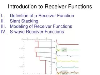
Goal: Find the Optimal S/R Spacings Interfaces 220 Elevation (m) 130 X (m) 3290m 3360m
INCO Velocity Model 0m V (m/s) 4500 Depth (m) 0 100m X (m) 0m 590m
Outline • Motivation • Forward Modeling • Refraction Tomography • Optimal S/R Spacings • Conclusions
Source at (200m, 3.003m) Source at (400m, 0.427m) 0 Time (s) 0.3 0 590 0 590 X (m) X (m)
First Arrivals Auto Picked 0 Time (s) 0.15 0 590 X (m)
Outline • Motivation • Forward Modeling • Refraction Tomography • Optimal S/R Spacings • Conclusions
Smoothing Size (in grid points) Iterations Grid Size (m) Schedule 1: 48*24 11 0.5 Schedule 2: 32*16 11 0.5 Schedule 3: 16*8 11 0.5 Dynamic Smoothing The schedules for dg=4m and ds=8m
dg=4m, ds=8m Schedule 1 0m V (m/s) 4500 0 120m 0m 590m
dg=4m, ds=8m Schedule 2 0m V (m/s) 4500 0 120m 0m 590m
dg=4m, ds=8m Schedule 3 0m V (m/s) 4500 0 120m 0m 590m
dg=4m, ds=8m Schedule 1 0m Num. of Rays 4000 0 120m 0m 590m
dg=4m, ds=8m Schedule 2 0m Num. of Rays 4000 0 120m 0m 590m
dg=4m, ds=8m Schedule 3 0m Num. of Rays 4000 0 120m 0m 590m
Sche 1 Sche 2 Sche 3 Residual vs. Iteration Number 0.014 Residual 0 0 35 Iteration Number
Outline • Motivation • Forward Modeling • Refraction Tomography • Optimal S/R Spacings • Conclusions
dg (m) ds (m) 1 2, 4 2 2, 4 4 4, 8 8 8, 16 12 12, 24 24 24, 48 S/R Spacings Tested
dg=1m, ds=2m 0m 120m 0m 590m
dg=1m, ds=4m 0m 120m 0m 590m
dg=2m, ds=2m 0m 120m 0m 590m
dg=2m, ds=4m 0m 120m 0m 590m
dg=4m, ds=4m 0m 120m 0m 590m
dg=8m, ds=8m 0m 120m 0m 590m
dg=12m, ds=12m 0m 120m 0m 590m
dg=12m, ds=24m 0m 120m 0m 590m
dg=24m, ds=24m 0m 120m 0m 590m
dg=24m, ds=48m 0m 120m 0m 590m
dg (m) ds (m) 1 2, 4 2 2, 4 High Res. 4 4, 8 8 8, 16 12 12, 24 Intermediate Res. 24 24, 48 Poor Res. S/R Spacings Categorized
dg=2m, ds=2m High Res. 0m 120m 0m 590m
dg=12m, ds=12 m Interm Res. 0m 120m 0m 590m
dg=24m, ds=24m Poor Res. 0m 120m 0m 590m
dg=2m, ds=2m High Res. 0m 120m 0m 200m
dg=12m, ds=12m Interm Res. 0m 120m 0m 200m
dg=24m, ds=24m Poor Res. 0m 120m 0m 200m
dg=2m, ds=2m High Res. 0m 120m 200m 400m
dg=12m, ds=12m Interm Res. 0m 120m 200m 400m
dg=24m, ds=24m Poor Res. 0m 120m 200m 400m
dg=2m, ds=2m High Res. 0m 120m 400m 590m
dg=12m, ds=12m Interm Res. 0m 120m 400m 590m
dg=24m, ds=24m Poor Res. 0m 120m 400m 590m
Outline • Motivation • Forward Modeling • Refraction Tomography • Optimal S/R Spacings • Conclusions
When ds, dg <= 12m, tomograms acceptable, resolution high When ds, dg > 24m, resolution very poor Recommend using ds, dg between 1~4 m for good vertical and horizontal resolution Conclusion
Acknowledgements We thank Utah Tomography and Modeling/Migration Consortium sponsors for their financial support