Dual Actuator EUI Systems Chapter 26
Dual Actuator EUI Systems Chapter 26. DSL 131. OBJECTIVES. Identify the engine families and OEMs that have used dual actuator EUIs. Describe the system layout and the primary components in a full authority, dual actuator EUI-fueled, engine management system. OBJECTIVES (Cont.).

Dual Actuator EUI Systems Chapter 26
E N D
Presentation Transcript
OBJECTIVES • Identify the engine families and OEMs that have used dual actuator EUIs. • Describe the system layout and the primary components in a full authority, dual actuator EUI-fueled, engine management system.
OBJECTIVES (Cont.) • Identify the truck engines using dual actuator EUI fueling from 2007 to 2010. • Identify the truck engines that currently (post-2010) use dual actuator EUI fueling. • Outline the role that the four primary subsystems play in managing a dual actuator EUI-fueled engine.
OBJECTIVES (Cont.) • Describe the operating principles of a four-terminal (dual-actuator) Delphi EUI. • Sequence the injection phases of a Delphi E3 injector. • Describe how the ECM manages duty cycle in dual actuator EUIs to control engine fueling.
OBJECTIVES (Cont.) • Outline some of the factors that govern the ECM fueling and engine management algorithm. • Perform some basic troubleshooting on VECTRO III and V-MAC IV EUI-fueled engines.
INTRODUCTION • The dominant fuel system of commercial truck diesel engines was the single actuator electronic unit injector (EUIs) system, but by 2007, more precise management of combustion was required.
View of the Left Side of a Dual Actuator EUI-Fueled Caterpillar C13 Engine
SYSTEM OVERVIEW • Mechanically-actuated, dual actuator EUIs have an effective pumping stroke managed and switched by the electronic control module (ECM) or electronic engine control unit (EECU).
Fuel Subsystem on a Mack Trucks EUI-Fueled Engine • Supply pump (external gear type) • Fuel tank • EECU • Fuel filter housing pad
Fuel Subsystem on a Mack Trucks EUI-Fueled Engine (Cont.) • Pre-filter • Primary fuel filter and water separator (under suction) • Secondary filter • Fuel gallery
Fuel Subsystem on a Mack Trucks EUI-Fueled Engine (Cont.) • Electronic unit injectors (EUIs) • Charging pressure control valve • Safety check valve • Non-return valve
Fuel Subsystem on a Mack Trucks EUI-Fueled Engine (Cont.) • Hand primer pump • Water-in-fuel (WIF) sensor • Dash-mounted water drain switch • Water separator drain valve
Fuel Subsystem on a Mack Trucks EUI-Fueled Engine (Cont.) • Bleeder valve • Charging pressure test measuring point • Fuel pressure sensor • Optional fuel heater
Fuel Subsystem on a Mack Trucks EUI-Fueled Engine (Cont.) • Valve peg (lock-off for servicing) • Non-return valve • Bleeding valve • Breather vent • Fuel return pipe
Block Diagram of the Dual Actuator EUI-Fueled C15 Engine Electronic Circuit
DDEC VI Schematic Showing the Two Module Engine Controller System Used To Manage their Dual Actuator EUI Fuel Systems
OUTPUT CIRCUIT • Output circuit devices affect the results of the computer processing cycle into action. • In an EUI fuel system, the primary engine outputs are the EUIs and commands to the exhaust aftertreatment hardware.
Mack Trucks 2010 MP8 Engine with Cylinder Head Cutaway to Show a Sectioned E3 Injector
CAUTION • Failure to reprogram fuel calibration codes when EUIs are replaced will result in the ECM/EECU using fuel flow data of the previous injector programming, which can result in engine fueling balance problems.
CAUTION • Always observe OEM instructions for draining the fuel manifold when removing EUIs from an engine cylinder head. • When an EUI is removed, the contents of the fuel charging rail end up in the engine cylinder if the cylinder head fuel gallery is not first drained.
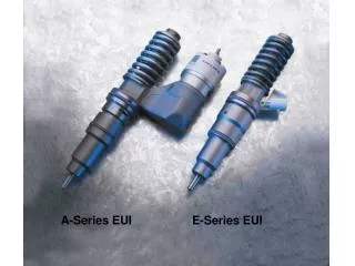
Installation of a Delphi E3 EUI • In describing the installation of an E3 dual actuator EUI, we are going to use a DDC post-2007 Series 60 engine as our example. • The procedure differs little from that used by the other two OEMs using this fuel system.
Apply a small amount of clean engine oilto the oil hole in the plunger.
SUMMARY • Dual actuator EUIs were introduced in 2007 and were used by Caterpillar in C11, C13, and C15 ACERT engines; by DDC in their 14-liter Series 60; and by the entire range of Volvo and Mack Trucks common platform engines. • The only OEM using Delphi E3 injectors after EPA model year 2010 (in the U.S./Canada markets) is Volvo-Mack.
SUMMARY (Cont.) • The numeric values used in Volvo engine family codes can be interpreted as the engine displacement in liters. • The VE-D11 code can be interpreted as follows: • V = Volvo • E = electronic • D = diesel • 11 = engine displacement in liters
SUMMARY (Cont.) • The numeric values used in Mack Trucks engine family codes can be interpreted as the engine displacement to the nearest 100 cubic inches displacement. • The MP-10 code can be interpreted as follows: • M = Mack • P = power • 10 = engine displacement in 100s of cubic inches • So the 10 is equivalent to 1,000 cubic inches, which is close to the 16.1 liters the engine displaces.
SUMMARY (Cont.) • The common platform Volvo engines are the VE-D11 (11-liter), VE-D13 (13-liter), and VE-D15 (15-liter) engines. • The common platform Mack Trucks engines are the MP7 (700 cu. in.), MP8 (800 cu. in.) and MP10 (1,000 cu. in.) engines.
SUMMARY (Cont.) • It should be noted that the Volvo-Mack common platform engines correlate as 11-liter/700 cu. in., 13-liter/800 cu. in., and 15-liter/1,000 cu. in. They are all metrically engineered and are differentiated primarily by paint job. • Dual actuator EUIs are also known as four-terminal EUIs. They are manufactured by Delphi and described as E3 injectors.
SUMMARY (Cont.) • The fuel subsystems supplying E3 injectors regardless of manufacturer use a gear-type transfer pump to create charging pressures. • However, because the fuel subsystem is used by some OEMs to supply aftertreatment dosing injectors, the charging pressures vary from a low of around 60 psi (415 kPa) to a high of 250 psi (1,724 kPa).
SUMMARY (Cont.) • ECM functions in Volvo and Mack Trucks E3-fueled engines are divided between two modules—A VCU (MID 144) interacts with the EECU (MID 128) to produce engine powertrain outcomes. • The EECU incorporates both the processing capability and output switching apparatus required to manage fueling and emissions controls on 2007 to 2010 engines. • Post-2010 engines use an aftertreatment module to manage DPF and SCR functions.
SUMMARY (Cont.) • The Volvo-Mack ECM/EECU houses the injector drivers and uses induction coils to spike the EUI actuation voltage to values around 100 V-DC in post-2007 engines. • The control cartridge in an E3 injector is known as a spill valve (SV) actuator. It is an ECM-controlled solenoid and valve that controls effective stroke either by trapping fuel in the EUI or by optioning it to the spill circuit.
SUMMARY (Cont.) • The nozzle control valve (NCV) actuator enables the ECM to manage the nozzle opening pressure (NOP) precisely . • The E3 NCV enables soft value NOPs permitting much higher NOP and nozzle closure pressures than would be possible with the hard value NOPs of single actuator EUIs.
SUMMARY (Cont.) • The E3 pressurizing phase requires the SV actuator to be energized. • During the pressurizing phase, fuel is not necessarily injected into the engine. • For fuel injection to take place, both the NCV and SV actuators must be energized.
SUMMARY (Cont.) • The E3 SV actuator may be energized several times during an injection pulse. This enables multipulse injection.
Any Questions ? • Thank You !