Dual Actuator EUI Systems (Extract) Chapter 26
Dual Actuator EUI Systems (Extract) Chapter 26. DSL 131. OBJECTIVES. Describe the system layout and the primary components in a full authority, dual actuator EUI-fueled, engine management system .

Dual Actuator EUI Systems (Extract) Chapter 26
E N D
Presentation Transcript
OBJECTIVES • Describe the system layout and the primary components in a full authority, dual actuator EUI-fueled, engine management system. • Outline the role that the four primary subsystems play in managing a dual actuator EUI-fueled engine. • Describe the operating principles of a four-terminal (dual-actuator) Delphi EUI. • Sequence the injection phases of a Delphi E3 injector. • Describe how the ECM manages duty cycle in dual actuator EUIs to control engine fueling.
INTRODUCTION • The dominant fuel system of commercial truck diesel engines was the single actuator electronic unit injector (EUIs) system, but by 2007, more precise management of combustion was required.
SYSTEM OVERVIEW • Mechanically-actuated, dual actuator EUIs have an effective pumping stroke managed and switched by the electronic control module (ECM) or electronic engine control unit (EECU). • They also control the nozzle opening pressure with a second solenoid assembly.
Fuel Subsystem on a Mack Trucks EUI-Fueled Engine • Supply pump (external gear type) • Fuel tank • EECU • Fuel filter housing pad • Pre-filter • Primary fuel filter and water separator (under suction) • Secondary filter • Fuel gallery • Electronic unit injectors (EUIs) • Charging pressure control valve • Safety check valve • Non-return valve • Hand primer pump • Water-in-fuel (WIF) sensor • Dash-mounted water drain switch • Water separator drain valve
Fuel Subsystem on a Mack Trucks EUI-Fueled Engine (Cont.) • Bleeder valve • Charging pressure test measuring point • Fuel pressure sensor • Optional fuel heater
Fuel Subsystem on a Mack Trucks EUI-Fueled Engine (Cont.) • Valve peg (lock-off for servicing) • Non-return valve • Bleeding valve • Breather vent • Fuel return pipe
OUTPUT CIRCUIT • Output circuit devices affect the results of the computer processing cycle into action. • In an EUI fuel system, the primary engine outputs are the EUIs and commands to the exhaust aftertreatment hardware.
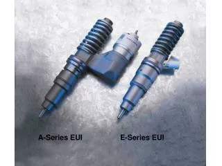
E3 EUI Nomenclature • The internal components of the dual actuator EUI are similar to the single actuator EUI. • The SV (spill valve) armature performs the same function as the solenoid in a signle actuator by controlling the effective plunger stroke. • A NCV (nozzle control valve) is added to control the NOP of the nozzle assembly. • A higher NOP makes for a better initial spray pattern and a cleaner cut off with smaller fuel droplets.
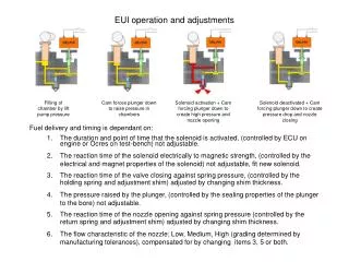
E3 EUI atRest Phase • When both the SV and the NCV are open, all fuel displaced by the plunger is returned to the fuel source.
E3 EUIPressurizing Phase • When pressurizing, the SV valve closes causing pressure to build. • Because the NCV is still open, pressure continues to develop, but injection does not occur.
Four-Terminal EUI Injection Phase • When both the SV and the NCV are closed, the nozzle is allowed to open, at a more appropriate pressure. • Fuel is now injected.
Mack Trucks 2010 MP8 Engine with Cylinder Head Cutaway to Show a Sectioned E3 Injector
CAUTION • Failure to reprogram fuel calibration codes when EUIs are replaced will result in the ECM/EECU using fuel flow data of the previous injector programming, which can result in engine fueling balance problems. • In other words, the computer may believe that a new, higher flowing, injector is a low flow unit and allow a longer effective stroke of the plunger causing that cylinder to overfuel.
CAUTION • Always observe OEM instructions for draining the fuel manifold when removing EUIs from an engine cylinder head. • When an EUI is removed, the contents of the fuel charging rail end up in the engine cylinder if the cylinder head fuel gallery is not first drained.
SUMMARY (Cont.) • It should be noted that the Volvo-Mack common platform engines correlate as 11-liter/700 cu. in., 13-liter/800 cu. in., and 15-liter/1,000 cu. in. They are all metrically engineered and are differentiated primarily by paint job. • Dual actuator EUIs are also known as four-terminal EUIs. They are manufactured by Delphi and described as E3 injectors.
SUMMARY (Cont.) • The fuel subsystems supplying E3 injectors regardless of manufacturer use a gear-type transfer pump to create charging pressures. • However, because the fuel subsystem is used by some OEMs to supply aftertreatment dosing injectors, the charging pressures vary from a low of around 60 psi (415 kPa) to a high of 250 psi (1,724 kPa).
SUMMARY (Cont.) • ECM functions in Volvo and Mack Trucks E3-fueled engines are divided between two modules—A VCU (MID 144) interacts with the EECU (MID 128) to produce engine powertrain outcomes. • The EECU incorporates both the processing capability and output switching apparatus required to manage fueling and emissions controls on 2007 to 2010 engines.
SUMMARY (Cont.) • The control cartridge in an E3 injector is known as a spill valve (SV) actuator. It is an ECM-controlled solenoid and valve that controls effective stroke either by trapping fuel in the EUI or by optioning it to the spill circuit. • The nozzle control valve (NCV) actuator enables the ECM to manage the nozzle opening pressure (NOP) precisely . • The E3 NCV enables soft value NOPs permitting much higher NOP and nozzle closure pressures than would be possible with the hard value NOPs of single actuator EUIs.
SUMMARY (Cont.) • The E3 pressurizing phase requires the SV actuator to be energized. • During the pressurizing phase, fuel is not necessarily injected into the engine. • For fuel injection to take place, both the NCV and SV actuators must be energized. • The E3 SV actuator may be energized several times during an injection pulse. This enables multipulse injection.
Any Questions ? • Thank You !