Download

1 / 18
180 likes | 333 Views
The LHCb Run Control System. An Integrated and Homogeneous Control System. The Experiment Control System. Is in charge of the Control and Monitoring of all parts of the experiment. DCS Devices (HV, LV, GAS, Cooling, etc.). Detector Channels. L0. TFC. Front End Electronics. Readout Network.

E N D
The LHCb Run Control System An Integrated and Homogeneous Control System
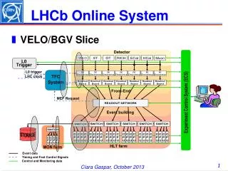
The Experiment Control System • Is in charge of the Control and Monitoring of all parts of the experiment DCS Devices (HV, LV, GAS, Cooling, etc.) Detector Channels L0 TFC Front End Electronics Readout Network Experiment Control System HLT Farm Storage Monitoring Farm DAQ External Systems (LHC, Technical Services, Safety, etc)
Some Requirements • Large number of devices/IO channels • Need for Distributed Hierarchical Control • De-composition in Systems, sub-systems, … , Devices • Local decision capabilities in sub-systems • Large number of independent teams and very different operation modes • Need for Partitioning Capabilities (concurrent usage) • High Complexity & Non-expert Operators • Need for Full Automation of: • Standard Procedures • Error Recovery Procedures • And for Intuitive User Interfaces
Design Steps • In order to achieve an integrated System: • Promoted HW Standardization (so that common components could be re-used) • Ex.: Mainly two control interfaces to all LHCb electronics • Credit Card sized PCs (CCPC) for non-radiation zones • A serial protocol (SPECS) for electronics in radiation areas • Defined an Architecture • That could fit all areas and all aspects of the monitoring and control of the full experiment • Provided a Framework • An integrated collection of guidelines, tools and components that allowed the development of each sub-system coherently in view of its integration in the complete system
ECS INFR. DCS TFC DAQ HLT LHC … SubDet1DCS SubDet2DCS SubDetNDCS SubDet1DAQ SubDet2DAQ SubDetNDAQ SubDet1LV SubDet1TEMP SubDet1GAS SubDet1FEE SubDet1RO … LVDev1 LVDev2 LVDevN FEEDev1 FEEDev2 FEEDevN Generic SW Architecture … Status & Alarms Commands Legend: ControlUnit DeviceUnit …
The Control Framework • The JCOP* Framework is based on: • SCADA System - PVSSII for: • Device Description (Run-time Database) • Device Access (OPC, Profibus, drivers) • Alarm Handling (Generation, Filtering, Masking, etc) • Archiving, Logging, Scripting, Trending • User Interface Builder • Alarm Display, Access Control, etc. • SMI++ providing: • Abstract behavior modeling (Finite State Machines) • Automation & Error Recovery (Rule based system) * – The Joint COntrols Project (between the 4 LHC exp. and the CERN Control Group) Device Units Control Units
Device Units DeviceUnit • Provide access to “real” devices: • The Framework provides (among others): • “Plug and play” modules for commonly used equipment. For example: • CAEN or Wiener power supplies (via OPC) • LHCb CCPC and SPECS based electronics (via DIM) • A protocol (DIM) for interfacing “home made” devices. For example: • Hardware devices like a calibration source • Software devices like the Trigger processes (based on LHCb’s offline framework – GAUDI) • Each device is modeled as a Finite State Machine
Hierarchical control ControlUnit • Each Control Unit: • Is defined as one or more Finite State Machines • Can implement rules based on its children’s states • In general it is able to: • Summarize information (for the above levels) • “Expand” actions (to the lower levels) • Implement specific behaviour& Take local decisions • Sequence & Automate operations • Recover errors • Include/Exclude children (i.e. partitioning) • Excluded nodes can run is stand-alone • User Interfacing • Present information and receive commands DCS … TrackerDCS MuonDCS MuonLV MuonGAS
Control Unit Run-Time • Dynamically generated operation panels(Uniform look and feel) • Configurable User Panelsand Logos • “Embedded” standard partitioning rules: • Take • Include • Exclude • Etc.
Operation Domains • Three Domains have been defined: • DCS • For equipment which operation and stability is normally related to a complete running periodExample: GAS, Cooling, Low Voltages, etc. • HV • For equipment which operation is normally related to the Machine state. Example: High Voltages • DAQ • For equipment which operation is related to a RUNExample: Readout electronics, High Level Trigger processes, etc.
Recover ERROR UNKNOWN NOT_READY Recover Configure Recover Switch_OFF ERROR NOT_READY ERROR NOT_READY CONFIGURING OFF OFF Reset Go_STANDBY1 RAMPING_STANDBY1 READY Switch_ON Switch_OFF STANDBY1 READY Start Stop Go_STANDBY2 RAMPING_STANDBY2 RUNNING STANDBY2 Go_READY RAMPING_READY READY FSM Templates • DCS Domain • HV Domain • DAQ Domain • All Devices and Sub-Systems have been implemented using one of these templates
ECS ECS: Run Control • Size of the Control Tree: • Distributed over ~150 PCs • ~100 Linux(50 for the HLT) • ~ 50 Windows • >2000 Control Units • >30000 Device Units • The Run Control can be seen as: • The Root node of the tree • If the tree is partitioned there can be several Run Controls. HV DCS TFC DAQ HLT LHC X X … … SubDet1DCS SubDetNDCS SubDet1DAQ SubDetNDAQ SubDet1
DAQ Partitioning • Creating a Partition • Allocate = Get a “slice” of: • Timing & Fast Control (TFC) • High Level Trigger Farm (HLT) • Storage System • Monitoring Farm • ECS Domain NOT_ALLOCATED Allocate ALLOCATING Deallocate Recover NOT_READY ERROR Configure CONFIGURING Reset READY StartRun StopRun ACTIVE StartTrigger StopTrigger RUNNING
Run Control User Interface • Matrix • Activity Domain X Sub-Detector Used forConfiguring all Sub-Systems
DAQ Configuration • Cold Start to Running takes ~4 mins • Slowest Sub-systems: • MUON FE Electronics • Did not use the recommended HW interface… • High Level Trigger • Startup and Configuration of ~10000 processes • Trigger Processes based on Offline Software • But a cold start is very rare: • Run is started well before “Stable Beams” • “Fast Run Change” mechanism • When “conditions” change • Takes ~5 seconds
LHCb Operations • Only 2 Operators on shift • The Shift Leader has two views of the system • Run Control UI • LHCb Status UI • Automation • In Sub-systems • HLT:Dead TriggerTasks/Nodes • HV:Tripped Channels • Centrally • Voltages dependingon LHC State • More will come…
Conclusions • LHCb has designed and implemented a coherent and homogeneous control system • The Run Control allows to: • Configure, Monitor and Operate the Full Experiment • Run any combination of sub-detectors in parallel in standalone • Can be completely automated (when we understand the machine) • Some of its main features: • Sequencing, Automation, Error recovery, Partitioning • Come from the usage of SMI++ (integrated with PVSS) • It’s being used daily for Physics data taking and other global or sub-detector activities
Sub-Detector Run Control • “Scan” Run