Chapter 6 - Analysis of Structures
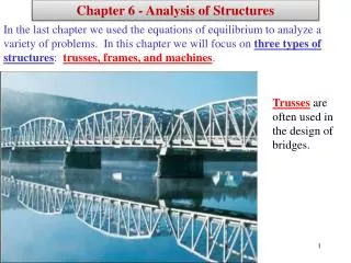
Chapter 6 - Analysis of Structures. In the last chapter we used the equations of equilibrium to analyze a variety of problems. In this chapter we will focus on three types of structures : trusses, frames, and machines . Trusses are often used in the design of bridges. Chapter 6 Objectives.

Chapter 6 - Analysis of Structures
E N D
Presentation Transcript
Chapter 6 - Analysis of Structures In the last chapter we used the equations of equilibrium to analyze a variety of problems. In this chapter we will focus on three types of structures: trusses, frames, and machines. Trusses are often used in the design of bridges.
Chapter 6 Objectives Students will be able to:1) Analyze trusses a) define a simple truss b) identify commonly-used trusses c) identify zero-force members d) determine forces in members using the Method of Joints e) determine forces in members using the Method of Sections2) Analyze frames a) define a frame b) identify multi-force members in frames c) use FBDs and equations of equilibrium to analyze each multi-force member or the entire frame3) Analyze machines a) define a machine b) identify multi-force members in machines c) use FBDs and equations of equilibrium to analyze each multi-force member or the entire machine
Chapter 6 – Three types of structures Chapter 6 – Structures in Equilibrium Ch. 1 – 5: Only external forces were considered Ch. 6: Both external and internal forces will be considered 3 type of structures will be considered: 1) Truss – a stationary structure made up of only 2-force members 2) Frame – a stationary structure containing at least one multi-force member (3 or more forces) 3) Machine – a structure that is designed to move or exert forces (such as a hand tool) containing at least one multi-force member (3 or more forces)
Trusses -Examples Trusses are commonly used to support roofs. For a given truss geometry and load, how can you determine the forces in the truss members and thus be able to select their sizes?
Trusses - Examples A more challenging question is that for a given load, how can we design the trusses’ geometry to minimize cost?
Trusses – Examples Trusses are also used in a variety of structures like cranes and the frames of aircraft or space stations.
Trusses – Terminology and Assumptions Trusses consist of members and joints and the entire truss is mounted on supports, as illustrated below. • The following assumptions will be made for trusses: • A truss is a stationary structure • Trusses should be rigid (holds its shape and will not collapse) • Trusses will be generally treated as 2D structures, although the analysis methods to be introduced can be applied to 3D trusses (space trusses) • A truss is made up of only 2-force members • All joints in the truss are pinned (thus the reaction at the pin has no moment) • All forces (loads) will be applied at the joints of a truss
Trusses – Terminology and Assumptions (continued) • The following assumptions will be made for trusses (continued) • Due to the constraints listed above, each member of the truss experiences only axial forces (along the axis of the member). This axial force is either one of tension (T) or compression (C). Forces in truss members will use the designations T or C.
Actual trusses Pinned (and bolted) connection Gusset plate • How good are the assumptions made previously? • Actual trusses are typically not pinned, but are instead bolted, nailed, riveted, or welded. A gusset plate (see Figure 6-1) may also be added to connect the members together at a joint. However, the members are designed primarily to bear axial loads and experience minimal twisting (moments), so our assumptions make for a good model of an actual truss. • Actual trusses also experience loading throughout the truss (called distributed loads) and not simply loading at the joints. But it will be shown in a later chapter that distributed loads can be easily represented by single loads at various points (such as the joints), so again our truss model is reasonable.
Roof Trusses The roof truss below is formed by two planar trusses connected by a series of purlins.
Bridge Trusses The bridge below is formed by two planar trusses. The load on the deck is first transmitted to stringers, then to floor beams, and finally to the joints B, C, and D of the two supporting side trusses.
Rigid Trusses It is important that trusses be rigid. A rigid truss will not collapse under application of a load. Non-rigid truss. May collapse under applied load. Rigid truss. Will not collapse under applied load.
Simple Trusses A simple trussis:- a rigid truss- a planar truss which begins with a triangular element and can be expanded by adding two members and a joint.- will satisfy the formula m = 2n – 3, where m = number of members and n = number of joints Simple truss Note: Not all rigid trusses are simple trusses. Sketch an example below (two simple trusses connected together).
Simple Trusses - continued Example: Begin with a simple triangle and form a larger simple truss. Show that m=2n-3 applies after each step
Anaylsis of Trusses – Method of Joints • Two methods will be introduced for analyzing trusses: • Method of joints • Method of sections • Method of joints • This is a systematic method for analyzing each joint in the truss in order to determine the forces in all members of the truss. • It is the best method if the forces in all members of the truss are to be determined. • Each joint is considered to be in equilibrium, but the joint is pinned and all member forces go through the joint, so no moments are experienced at the joint. Therefore, only 2 equations are applied in analyzing the joint (for a 2D truss): Fx = 0 Fy = 0
Method of Joints - Procedure • 1) Analyze the entire truss as a rigid body to find the external reactions (not always necessary) • 2) Pick the first joint to analyze • A) Since only two equations are available (Fx = 0 and Fy = 0), look for joints that only have two unknowns • B) Draw a FBD at the joint to be analyzed. • C) Show each member force in tension. • If the result is +, then the answer agrees with the way the force was drawn, so the force is in tension (attach a T to the answer). • If the result is -, then the answer disagrees with the way the force was drawn, so the force is in compression (attach a C to the answer). • Express all final answers as positive with either T or C attached. • Note: you could similarly draw the forces in compression and a + or – answer would again indicate agreement or disagreement. • 3) Continue analyzing additional joints in the truss until all member forces have been determined. Warning: If you determine that FAB = 200 lb T, be sure to show the force in tension when analyzing both joint A and joint B (so the actual direction of the force is reversed in the FBDs).
Example – Method of Joints Determine the force in each member of the truss and state if the members are in tension (T) or compression (C). Use P1 = 800 lb and P2 = 400 lb.
Zero-force members • Certain truss members may be subjected to zero force under certain loading conditions. • Recognizing zero-force members can simplify the analysis of the truss. • Zero-force members are often more slender than main truss members. • Why would zero-force members be used? • To provide stability to a truss during construction • To stiffen the truss • To provide support to a truss if loading conditions change (such as due to snow or wind force on a roof, loading on the deck of a bridge, etc.) In other words, the zero-force members may not be zero-force members when the loading changes.
Recognizing zero-force members: If only two members form a truss joint and no external load or support reaction is applied to the joint, the members must be zero-force members. Example: We can quickly tell that members AF, AB, DE, and DC are zero-force members in the truss below. (Align the y-axis with AF and summing forces in the x-direction shows that FBA = 0 as shown below.)
Recognizing zero-force members(continued): If three members form a truss joint for which two of the members are collinear, the third member is a zero-force member provided no external force or support reaction is applied to the joint. Summing forces in the x and y directions with one axis along the collinear members will quickly verify this result. Example: We can quickly tell that members AD and AC are zero-force members in the truss below. (If the y-axis is aligned with BCDE, then summing forces in the z-direction shows that FDA = 0 as shown below.)
Example – Finding zero-force members in trusses For the given loading, determine the zero-force members in the Pratt roof truss. Explain your answers using appropriate joint free-body diagrams.
Example – Method of Joints Determine the force in each member of the truss and state if the members are in tension (T) or compression (C). Before you begin, are there any zero-force members?
Analyzing Trusses – Two Methods • Trusses can be analyzed using either : • The Method of Joints - this is generally the best method if you need to find the forces in all of the truss members. • The Method of Sections -this is generally the best method if you need to find the forces in only a few members of the truss, especially if they are near the middle of the truss.
THE METHOD OF SECTIONS In the method of sections, a truss is divided into two partsby taking an imaginary “cut” (shown here as a-a) through the truss. Since truss members are subjected to only tensile or compressive forces along their length, the internal forcesat the cut members will also be either tensile or compressive with the same magnitude.
Method of Sections – Analysis Procedure 1. Decide how you need to “cut” the truss. This is based on: a) where you need to determine forces, and, b) where the total number of unknowns does not exceed three (in general). 2. Decide which side of the cut truss will be easier to work with (minimize the number of reactions you have to find). 3. If required, determine any necessary support reactions by drawing the FBD of the entire truss and applying the equations of equilibrium.
Method of Sections – Analysis Procedure (continued) 4. Draw the FBD of the selected part of the cut truss. We need to indicate the unknown forces at the cut members. Initially we may assume all the members are in tension, as we did when using the method of joints. Upon solving, if the answer is positive, the member is in tension as per our assumption. If the answer is negative, the member must be in compression. (Please note that you can also assume forces to be either tension or compression by inspection as was done in the figures above.)
Method of Sections – Analysis Procedure (continued) 5. Apply the scalar equations of equilibrium to the selected cut section of the truss to solve for the unknown member forces. Please note, in most cases it is possible to write one equation to solve for one unknown directly. So look for it and take advantage of such a shortcut! Recall that there are several choices for 2D equations of equilibrium as listed below: (most common)
Example – Method of Sections The Howe bridge truss is subjected to the loading shown. Determine the force in members HI, HB, and BC, and state if the members are in tension or compression.
Example – Method of Sections The tower truss is subjected to the loads shown. Determine the force in members BC, BF, AND FG, and state if the members are in tension or compression. The left side ABCD stands vertical.
Common trusses: The text shows several commonly-used trusses. Look around the city to see if you spot any of these trusses used to support bridges, signs, roofs, or other structures. Howe roof truss Howe bridge truss Pratt bridge truss Pratt roof truss
Common trusses: (continued) Fink roof truss Baltimore bridge truss K bridge truss Warren bridge truss
Common trusses: (continued) Howe scissors roof truss Gambrel roof truss Polynesian or duopitch roof truss Mansard roof truss
Common trusses: (continued) Two Pratt trusses are used (above) to construct this pedestrian bridge. These Howe trusses are used (to the right) to support the roof of the metal building. Note how the members come together at a common point on the gusset plate and how the roof purlins transmit the load to the joints.
Frames and Machines - Definitions Frame Machine Frames and machines are two common types of structures that have at least one multi-force member. (Recall that trusses have only two-force members). Frames are generally stationary and support external loads. Machinescontain moving partsand are designed to alter the effect of forces.
Application - Frames Frames are commonly used to support various external loads. How is a frame different than a truss? To be able to design a frame, you need to determine the forces at the joints and supports.
Frames B A C W D E Frames are stationary structures containing at least one multi-force member. They are typically designed to support some sort of load. (Recall that trusses are made of only 2-force members). Example: The structure below is a frame because it is a stationary structure that supports a load and it contains at least one multiforce member. Fill in the table below indicating which members are multiforce members and which are 2-force members.
Example: (continued) Draw a FBD for members ABC and CDE. B A C W D E
Frames – Analysis Procedure 1) Draw a FBD of the entire structure in order to determine the external reactions. In some cases, only a partial solution is possible (statically indeterminate structure). 2) Draw a FBD for each multi-force member and analyze it using 3 equations of equilibrium. Notes: A) If a load is applied at a joint, place on any one of the members. B) In some cases only a partial solution may be possible, but it is still important to solve for any reactions possible since they might be useful in analyzing another multi-force member. C) Be sure to reverse the direction of the reactions as they are transferred from one multi-force member to another. D) Remember that the direction of the force is known in a 2-force member, so if a 2-force member connects to a multi-force member, the reaction is represented with only one unknown.
Example – Analyzing a Frame The frame below supports a 50-kg cylinder. Find the reactions that the pins exert on the frame at A and D.
Example – Analyzing a Frame Determine the horizontal and vertical components of force that the pins A, B, and C exert on the frame. The cylinder has a mass of 80 kg. The pulley has a radius of 0.1m.
Machines • Machines are structures that are: • designed to move • used to modify or transmit forces • contain at least one multi-force member • generally not supported, so there may be no external reactions • Examples of machines would include some hand tools (such as pliers), construction equipment (backhoe, front-end loader, etc.), pulleys, and other tools that are not attached to supports. Machines – Analysis Procedure • The same as for frames, except that there are no external reactions. • In other words, analyze one multi-force member at a time and transfer the results to other multi-force members.
Applications - Machines “Machines,” like those above, are used in a variety of applications. How are they different from trusses and frames?
Example – Analyzing a Machine 1.5” 60 lb 4” 60 lb Analyze the simple pliers shown below. If 60 lb forces are applied to the handles as shown, determine the forces applied by the jaws to a bolt. Calculate the “mechanical advantage.”
Example – Analyzing a Machine Analyze the “vice grips” shown below. If 60 lb forces are applied to the handles, determine the forces applied by the jaws to a bolt. Calculate the “mechanical advantage.”
Example – Analyzing a Machine (work in class if time allows) The tractor shovel carries a 500-kg load of soil, having a center of gravity at G. Compute the forces developed in the hydraulic cylinders IJ and BC due to this loading.
Pulleys • Pulleys are examples of simple machines. • Recall that an ideal pulley simply redirects a force. • Belt friction and bearing friction are assumed to be negligible so the tension on either side of the pulley is the same. • If a pulley system has multiple ropes or cables, each rope or cable should be represented with a different tension (T1, T2, T3, etc.,) • The key to analyzing pulley problems is the use of the Free Body Diagram (FBD). Draw a FBD for each part of the pulley being analyzed and then analyze each FBD.
Example – Pulley Problem Determine the tension T in each case below to support a 100 lb block.
Example – Pulley Problem T 100 lb Determine the tension T in the rope below to support a 100 lb block.
Example – Pulley Problem Determine the force P required to support a 20 lb block.