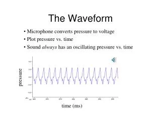
Download
1 / 23
230 likes | 395 Views
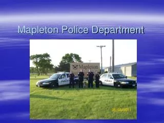
Tomostatic Waveform Tomography for Mapleton, Utah data. Jianming Sheng, and Maike Buddensiek. University of Utah. Feb. 5, 2004. Outline. Motivation. Data Preprocessings. Waveform Tomogram. Summary. First-break + First-peak. 0. 2500. Depth (m). 500. m/s. 45. 0. Distances (m). 80.

E N D
Tomostatic Waveform Tomography for Mapleton, Utah data Jianming Sheng, and Maike Buddensiek University of Utah Feb. 5, 2004
Outline Motivation Data Preprocessings Waveform Tomogram Summary
First-break + First-peak 0 2500 Depth (m) 500 m/s 45 0 Distances (m) 80
Observed Predicted Motivations • Produce better seismic image by fitting waveforms
Recorded CSG # 49 0 168 shots 168 receiver Interval: 5m Time (sec.) dt: 0.5 ms length: 1s 0.15 Geophone # 20 160
Outline Motivation Data Preprocessings Waveform Tomogram Summary
Data Preprocessings • Instrument caused amplitude anomalies
Amplitude Vs. Traveltime 40 Dashed: Fitted Solid: Observed Log-Amplitude 20 0 0.09 Traveltime (sec.)
Data Preprocessings • Instrument caused amplitude anomalies • Earth attenuation
Frequency Spectrum Vs. Offset 0.0 Frequency (Hz) 100 0 60 Offset (m)
Spectrum variance Attenuation factor Centroid frequency Attenuation Compensation Liao and McMechan (1997)
Q=24.0013 Frequency vs. Traveltime 85 Frequency (Hz) 40 0 0.1 Traveltime (sec.)
multiply to spectrum multiply for the geometrical spreading Data Preprocessings • Instrument caused amplitude anomalies • Earth attenuation • Transform data to 2D format
Preprocessed CSG # 49 0 Time (sec.) 0.15 Geophone # 20 160
Frequency Spectrum Vs. Offset 0.0 Frequency (Hz) 100 0 60 Offset (m)
Frequency Spectrum Vs. Offset 0.0 Frequency (Hz) 100 0 60 Offset (m)
Outline Motivation Data Preprocessings Waveform Tomogram Summary
Selected receiver Convolution Misfit Function Frazer and Sun, 1998
Waveform Tomogram 0 2500 Depth (m) 500 m/s 45 0 Distances (m) 80
First-break + First-peak 0 2500 Depth (m) 500 m/s 45 0 Distances (m) 80
Outline Motivation Data Preprocessings Waveform Tomogram Summary
Summary • The waveform tomogram does not show • much improvement compared to the first- • break and first-peak tomogram. • Elastic modeling code is needed.
Acknowledgment I thank the sponsors of the 2003 UTAM Consortium for their financial support .