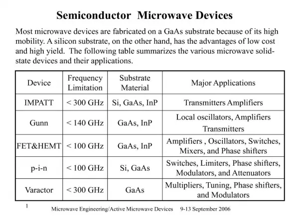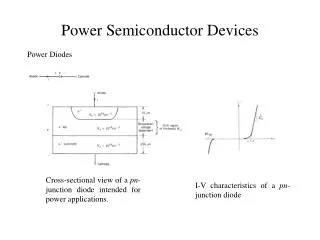
Semiconductor Devices
Semiconductor Devices. Atoms and electricity Semiconductor structure Conduction in semiconductors Doping epitaxy diffusion ion implantation Transistors MOS CMOS Implementing logic functions. Electricity. Electricity is the flow of electrons

Semiconductor Devices
E N D
Presentation Transcript
Semiconductor Devices • Atoms and electricity • Semiconductor structure • Conduction in semiconductors • Doping • epitaxy • diffusion • ion implantation • Transistors • MOS • CMOS • Implementing logic functions
Electricity • Electricity is the flow of electrons • Good conductors (copper) have easily released electrons that drift within the metal • Under influence of electric field, electrons flow in a current • magnitude of current depends on magnitude of voltage applied to circuit, and the resistance in the path of the circuit • Current flow governed by Ohm’s Law V = IR + electron flow direction -
Electron Bands • Electrons circle nucleus in defined shells • K 2 electrons • L 8 electrons • M 18 electrons • N 32 electrons • Within each shell, electrons are further grouped into subshells • s 2 electrons • p 6 electrons • d 10 electrons • f 14 electrons • electrons are assigned to shells and subshells from inside out • Si has 14 electrons: 2 K, 8 L, 4 M L K M shell d p s 10 6 2
Semiconductor Crystalline Structure • Semiconductors have a regular crystalline structure • for monocrystal, extends through entire structure • for polycrystal, structure is interrupted at irregular boundaries • Monocrystal has uniform 3-dimensional structure • Atoms occupy fixed positions relative to one another, but are in constant vibration about equilibrium
Semiconductor Crystalline Structure • Silicon atoms have 4 electrons in outer shell • inner electrons are very closely bound to atom • These electrons are shared with neighbor atoms on both sides to “fill” the shell • resulting structure is very stable • electrons are fairly tightly bound • no “loose” electrons • at room temperature, if battery applied, very little electric current flows
Conduction in Crystal Lattices • Semiconductors (Si and Ge) have 4 electrons in their outer shell • 2 in the s subshell • 2 in the p subshell • As the distance between atoms decreases the discrete subshells spread out into bands • As the distance decreases further, the bands overlap and then separate • the subshell model doesn’t hold anymore, and the electrons can be thought of as being part of the crystal, not part of the atom • 4 possible electrons in the lower band (valence band) • 4 possible electrons in the upper band (conduction band)
Energy Bands in Semiconductors • The space between the bands is the energy gap, or forbidden band
Insulators, Semiconductors, and Metals • This separation of the valence and conduction bands determines the electrical properties of the material • Insulators have a large energy gap • electrons can’t jump from valence to conduction bands • no current flows • Conductors (metals) have a very small (or nonexistent) energy gap • electrons easily jump to conduction bands due to thermal excitation • current flows easily • Semiconductors have a moderate energy gap • only a few electrons can jump to the conduction band • leaving “holes” • only a little current can flow
Insulators, Semiconductors, and Metals (continued) Conduction Band Valence Band Conductor Semiconductor Insulator
Hole - Electron Pairs • Sometimes thermal energy is enough to cause an electron to jump from the valence band to the conduction band • produces a hole - electron pair • Electrons also “fall” back out of the conduction band into the valence band, combining with a hole pair elimination pair creation hole electron
Improving Conduction by Doping • To make semiconductors better conductors, add impurities (dopants) to contribute extra electrons or extra holes • elements with 5 outer electrons contribute an extra electron to the lattice (donor dopant) • elements with 3 outer electrons accept an electron from the silicon (acceptor dopant)
Improving Conduction by Doping (cont.) • Phosphorus and arsenic are donor dopants • if phosphorus is introduced into the silicon lattice, there is an extra electron “free” to move around and contribute to electric current • very loosely bound to atom and can easily jump to conduction band • produces n type silicon • sometimes use + symbol to indicate heavier doping, so n+ silicon • phosphorus becomes positive ion after giving up electron
Improving Conduction by Doping (cont.) • Boron has 3 electrons in its outer shell, so it contributes a hole if it displaces a silicon atom • boron is an acceptor dopant • yields p type silicon • boron becomes negative ion after accepting an electron
Epitaxial Growth of Silicon • Epitaxy grows silicon on top of existing silicon • uses chemical vapor deposition • new silicon has same crystal structure as original • Silicon is placed in chamber at high temperature • 1200 o C (2150 o F) • Appropriate gases are fed into the chamber • other gases add impurities to the mix • Can grow n type, then switch to p type very quickly
Diffusion of Dopants • It is also possible to introduce dopants into silicon by heating them so they diffuse into the silicon • no new silicon is added • high heat causes diffusion • Can be done with constant concentration in atmosphere • close to straight line concentration gradient • Or with constant number of atoms per unit area • predeposition • bell-shaped gradient • Diffusion causes spreading of doped areas top side
Diffusion of Dopants (continued) Concentration of dopant in surrounding atmosphere kept constant per unit volume Dopant deposited on surface - constant amount per unit area
Ion Implantation of Dopants • One way to reduce the spreading found with diffusion is to use ion implantation • also gives better uniformity of dopant • yields faster devices • lower temperature process • Ions are accelerated from 5 Kev to 10 Mev and directed at silicon • higher energy gives greater depth penetration • total dose is measured by flux • number of ions per cm2 • typically 1012 per cm2 - 1016 per cm2 • Flux is over entire surface of silicon • use masks to cover areas where implantation is not wanted • Heat afterward to work into crystal lattice
Hole and Electron Concentrations • To produce reasonable levels of conduction doesn’t require much doping • silicon has about 5 x 10²² atoms/cm3 • typical dopant levels are about 1015 atoms/cm3 • In undoped (intrinsic) silicon, the number of holes and number of free electrons is equal, and their product equals a constant • actually, ni increases with increasing temperature • This equation holds true for doped silicon as well, so increasing the number of free electrons decreases the number of holes np = ni2
Metal-Oxide-Semiconductor Transistors • Most modern digital devices use MOS transistors, which have two advantages over other types • greater density • simpler geometry, hence easier to make • MOS transistors switch on/off more slowly • MOS transistors consist of source and drain diffusions, with a gate that controls whether the transistor is on Gate S D metal n+ n+ silicon dioxide p monosilicon
+ S D + n+ n+ p - MOS Transistors (continued) • Making gate positive (for n channel device) causes current to flow from source to drain • attracts electrons to gate area, creates conductive path • For given gate voltage, increasing voltage difference between source and drain increases current from source to drain
Complementary MOS Transistors • A variant of MOS transistor uses both n-channel and p-channel devices to make the fundamental building block (an inverter, or not gate) • lower power consumption • symmetry of design • If in = +, n-channel device is on, p-channel is off, out is connected to - • If in = -, n-channel is off, p-channel is on, out is connected to + • No current flows through battery in either case!! P out in N
CMOS (continued) • CMOS geometry (and manufacturing process) is more complicated • Lower power consumption offsets that • Bi-CMOS combines CMOS and bipolar (another transistor type) on one chip • CMOS for logic circuits • Bi-polar to drive larger electrical circuits off the chip S D S D n+ n+ p+ p+ n p
Logic Functions Using CMOS p A p B out two input NAND - if both inputs 1, both p-channel are off, both n-channel are on, out is negative; otherwise at least one p-channel is on and one n-channel off, and out is positive n n input 0 input 1