Insulators and HV overhead lines
440 likes | 488 Views
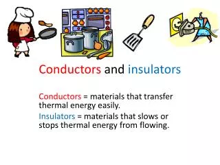
Insulators and HV overhead lines. Condition monitoring. Insulators. Three main forms. Gaseous – vacuum, nitrogen, argon, SF 6 Liquid – mineral and vegetable oils Solid – glass, ceramic, paper, mica. Purpose – to absorb energy generated under highly stress

Insulators and HV overhead lines
E N D
Presentation Transcript
InsulatorsandHV overhead lines Condition monitoring
Three main forms • Gaseous – vacuum, nitrogen, argon, SF6 • Liquid – mineral and vegetable oils • Solid – glass, ceramic, paper, mica
Purpose – to absorb energy generated under highly stress Gases absorb radiation and electrons at specific energies Reasons for ionisation of gas Electric field acceleration causing collision of charged atoms or electrons and neutral atoms Photo-ionisation Interaction of metastable atoms and neutral species Thermal ionisation Recombination processes Cathodic photoelectric emission Thermionic emission Field emission More specific information available in Kuffel Gaseous insulation
Gaseous insulation (2) • Electron affinity of an element is dependent upon its electron shell construction • H » H- -72 kJ/mole • O » O- -135 kJ/mole • F » F- -330 kJ/mole
Gaseous insulation (3) • Townsend and Paschen developed characteristic information on breakdown of gases under high electric fields
Liquid insulation • Electronic breakdown • Stress enhancement from suspended particulates • Cavity breakdown • Electro-convection and electro-hydrodynamic models • Static electrification
Liquid insulation (2) • Electronic breakdown – field emission from cathodic electrode surfaces inject electrons into the liquid, ionisation from collision with electrical field accelerated electrons cause breakdown • Stress enhancement from suspended particulates – spherical or fibrous particulates affect field intensities in their vicinity and reduce the breakdown strength from pure material values
Liquid insulation (3) • Cavity breakdown – cavities are gas bubbles generated by localised thermal excitation or electro-thermo-chemical reactions, these are less able to withstand the electric field • Electro-convection and electro-hydrodynamic models – as dielectrics are generally non-polar liquids they have the ability to store any charge injected from electrodes, the movement of these charged species under the convection and hydrodynamic movement of the liquid will determine stress enhancement
Liquid insulation (4) • Static electrification – insulating oils in transformers become charged as they pass through filters, pumps, etc. In contact with paper and pressboard, the oil stays positively charged with negative charge transferring to the solid insulator. New oil and oil with additives has been found to be less prone to this problem.
Solid insulation • Intrinsic breakdown • Streamer breakdown • Electromechanical breakdown • Edge breakdown and treeing • Thermal breakdown • Erosion breakdown • Tracking
Solid insulation (2) • Intrinsic breakdown – for homogeneous materials with no faults/inclusions intrinsic strength measured by slowly increasing voltage until breakdown occurs, determined by properties of material and temperature. Assumed to arise from electron dissociation from structure, crossing from valence to conduction band.
Solid insulation (3) • Streamer breakdown – Occurs in embedded electrode systems, where a cathodic electron has sufficiently long pathlength to traverse the insulation from cathode to anode (c.f. streamer theory in gaseous systems)
Solid insulation (4) • Electromechanical breakdown – Occurs where charge trapped within the insulation cause an attractive force greater than the material can withstand.
Solid insulation (5) • Edge breakdown and treeing – Occurs at regions where dissimilar materials cause a breakdown in the weaker material. Treeing is a gas filled channel formed in solid material – structure varies with material and field strength
Thermal breakdown – Occurs where power losses cause heating of the insulation system, affecting material properties. Thermal stability is field dependent, and is higher under dc than ac voltage Thermal voltage MV/cm Material ac Muscovite mica 7 - 18 HV steatite 9.8 High-grade porcelain 2.8 Capacitor paper 3.4 – 4 Polyethylene 3.5 Acrylic resins 0.3 - 1 Solid insulation (5)
Solid insulation (6) • Erosion breakdown – Occurs from cavities in insulation materials or at material boundaries. Cavity filled with gas or liquid, which breaks down more easily, surface of cavity reacts to electro-chemical events and erosion of the system results. Surface roughening exacerbates field stresses in the void.
Solid insulation (7) • Tracking – due to formation of conductive paths on the surfaces of insulation components. Could arise from carbonisation of insulator, contamination of external surfaces or metallic deposition from moving parts.
Insulators in Overhead lines • Source – JST Looms, “Insulators for High Voltages”, Peter Peregrinus Ltd
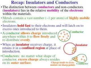
Function • Mechanical and electrical purposes • Ideally non-conductive element • External surface – contamination, produces non-linear resistance, hence, leakage current • Leakage current – heat and electrochemical change • Erosion of surface or flashover
Design (1) • Profile needed to overcome pollution and leakage current • A variety of convoluted profiles exist for string (cap and pin) insulators - varying the length of the skirts slightly improves performance, some designs produce acoustic resonances, desert discs (with open profiles) do badly in slat fog testing
Design (2) • Longrod or line post insulators • Poorer creepage than equivalent cap and pin • Helical sheds seem worse than expected – washing off of pollution not efficient
Materials • Ceramic / Glass • Polymeric – grp and silicon rubber • Glass and ceramic have high mechanical strength and high resistance to chemical attack but are brittle and readily wettable • Polymerics can be prone to chemical and photoelectric attack, low mechanical strength, degradation produces conductive tracks • Failure rate – 0.1% failure per annum • Failure position dependent – electrical stress
Adverse conditions • Ability to prevent/withstand flashover results from: • Profile – “best shape” is site dependent • Attitude – angular displacement • Surface properties – hydrophobicity, roughness
Flashover prevention • Optimise shape and creepage • Washing of insulators – from bottom to top to prevent polluted run off water causing flashover • Surface treatment – grease, controlled viscosity pertolatum gel, silicone paste • Hybrid insulators – ceramic core with polymeric coating, still at investigation stage to determine long term effects • Resistive glazes – only used where other methods not applicable
Tower string insulator • Arcing horns provide protection to insulators
Model of string • String insulator model – without and with guard ring
Line materials • Copper • Aluminium • Steel-cored aluminium • Copper-clad steel • Cadmium copper • Phosphor bronze • Galvanized steel
Line supports • UK 33kV supports • Wooden poles (winter felled, red fir, pressure impregnated with creosote) • Single, A frame and H frame • Pin type ceramic insulators (cheaper than string suspension insulators up to 50kV) • Lifetime dependent upon environmental conditions
UK Grid lines over 132kV • Standard painted, or galvanised, steel tower design • Wide base to cope with vertical, transverse and longitudinal stresses • Steel-cored aluminium cables held by glass/ceramic tension/suspension units • Number of cap and pin units, each 250mm diameter, dependent upon site conditions (pollution) and voltage
Line route selection • Determined by environmental and aesthetic considerations • Computer programs now used in industry to take such factors into account • Overhead preferred by industry on cost grounds but environmental impact should also be compared
Transmission route parameters • US figures • Index = Loading / RoW width x Tower height
Twin conductor advantages • Line inductance and inductive reactance reduced by 25% • Corona inception voltage 5-10% higher • More current carried per unit mass of conductor • Amplitude and duration of high frequency vibration reduced
Twin conductor disadvantages • Increased wind and ice loading • Suspension more complex • Tendency to dance increased • Above 250kV advantages outweigh disadvantages, hence twin bundles for 275kV and quads for 400kV
Catenary line sag-tension • See H M Ryan, Appendix 5.3
Effect of environment on line sag • Increased temperature causes expansion of conductor, increasing sag • Icing of conductor increases weight, increasing sag • Calculation to take account of 80km.hr -1 winds perpendicular to lines with a coating of 3.75mm ice at a temperature of -5°C is standard on UK lines
Electrical fields • The 30 metre tower shown is used to suspend two circuit 275 kV high voltage transmission lines. • The equipotential-lines connect points in space with the same induced voltage. The value of the induced voltage is given in kV rms. • The equipotential line form depends on the shape and configuration of the tower and on the distribution of the phases. • The equipotentials are calculated by a program used at NKF,
Electrical discharges • Radio interference • Corona losses
Monitoring lines • Thermal imaging is being used to identify discharge events on string insulators • Fly-pass 3D imaging used to ensure clearance from ground and tree growth • New device suggested to increase tension in cable to combat sag increase