Download
1 / 66
660 likes | 761 Views
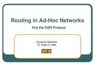
Chapter 2 Routing in Ad hoc Networks. Table of Contents. Each color represents range of transmission of a device. A. A. S. S. B. B. D. D. MH S uses B to communicate with MH D. Illustration of Multi-hop MANET. Due to movement of MHs, S now uses A and B to reach D. Topology-Based

E N D
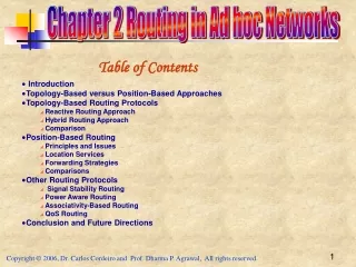
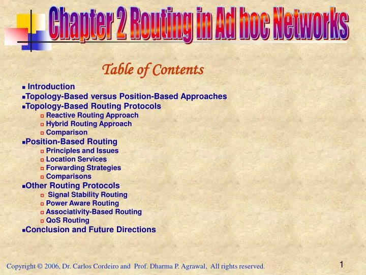
Chapter 2 Routing in Ad hoc Networks Table of Contents
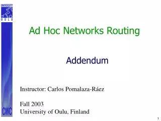
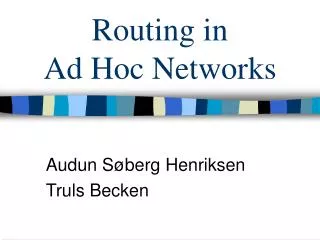
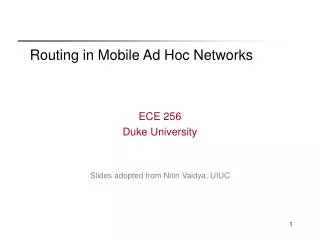
Each color represents range of transmission of a device A A S S B B D D • MH S uses B to communicate with MH D Illustration of Multi-hop MANET Due to movement of MHs, S now uses A and B to reach D
Topology-Based Depends on the information about existing links Position-Based Approaches Proactive (or table-driven) Traditional distributed shortest-path protocols Maintain routes between every host pair at all times Based on periodic updates; High routing overhead Example: DSDV (destination sequenced distance vector) Reactive (On-Demand) protocols Determine route if and when needed Source initiates route discovery Example: DSR (dynamic source routing) Hybrid protocols Adaptive: Combination of proactive and reactive Example: ZRP (zone routing protocol) Routing Protocols
Topology-Based Depends on the information about existing links Position-Based Approaches Proactive (or table-driven) Node experiences minimal delay whenever a route is needed May not always be appropriate for high mobility Distance-vector or link-state routing Reactive (or on-demand) Consume much less bandwidth Delay in determining a route can be substantially large Hybrid protocols MHs determine their own position through GPS Position-based routing algorithms overcome some of the limitations Routing Approaches
Destination-Sequenced Distance-Vector (DSDV) Protocol A proactive hop-by-hop distance vector routing protocol Requires each MH to broadcast routing updates periodically Every MH maintains a routing table for all possible destinations and the number of hops to each destination Sequence numbers enable the MHs to distinguish stale routes from new ones To alleviate large network update traffic, two possible types of packets: full dumps or small increment packets The route labeled with the most recent sequence number is always used In the event that two updates have the same sequence number, the route with the smaller metric is used in order to optimize (shorten) the path Proactive Routing Approaches
Assume that MH X receives routing information from Y about a route to MH Z Let S(X) and S(Y) denote the destination sequence number for MH Z as stored at MH X, and as sent by MH Y with its routing table to node X, respectively Z X Y Destination-Sequenced Distance-Vector (DSDV)
MH X takes the following steps: If S(Y) > S(X), then X ignores the routing information received from Y If S(Y) = S(X), and cost of going through Y is smaller than the route known to X, then X sets Y as the next hop to Z If S(Y) < S(X), then X sets Y as the next hop to Z, and S(X) is updated to equal S(Y) Z X Y Destination-Sequenced Distance-Vector (DSDV)
The Wireless Routing Protocol A table-driven protocol with the goal of maintaining routing information among all MHs Each MH maintains four tables: Distance, Routing, Link-cost, and the Message Retransmission List (MRL) tables Each entry in MRL contains the sequence number of the update message MHs keep each other informed of all link changes through the use of update messages MHs learn about their neighbors from acknowledgments and other messages If a MH does not send any message for a specified time period, it must send a hello message to ensure connectivity Proactive Routing Approaches
Topology Broadcast based on Reverse Path Forwarding Protocol Considers broadcasting topology information (including link costs and up/down status) to all MHs Each link-state update is sent on every link of the network though flooding Communication cost of broadcasting topology can be reduced if updates are sent along spanning trees Messages are broadcast in the reverse direction along the directed spanning tree formed by the shortest paths from all nodes to source Messages generated by a given source are broadcast in the reverse direction along the directed spanning tree formed by the shortest paths from all MHs (nodes) to the source Proactive Routing Approaches
The Optimized Link State Routing Protocol Based on the link state algorithm All links with neighboring MHs are declared and are flooded in the entire network Minimizes flooding of this control traffic by using only the selected MHs, called multipoint relays Only normal periodic control messages sent Beneficial for the traffic patterns with a large subset of MHs are communicating with each other Good for large and dense networks An in-order delivery of its messages is not needed as each control message contains a sequence number Proactive Routing Approaches
Multipoint Relays Minimize the flooding of broadcast packets in the network by reducing duplicate retransmissions in the same region Each MH selects a set of neighboring MHs, to retransmit its packets and is called the multipoint relays (MPRs) This set can change over time and is indicated by the selector nodes in their hello messages Each node selects MPR among its one hop bi-directional link neighbors to all other nodes that are two hops away Proactive Routing Approaches
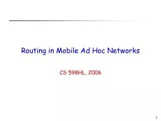
Illustration of Multipoint Relays Retransmitting node or multipoint relays N One hop node NOT selected for relays Two hop nodes
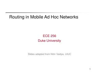
Dynamic Source Routing • When MH S wants to send a packet to MH D, but does not know a route to D, MH S initiates a route discovery • Source node S floods Route Request (RREQ) • Each MH appends own identifier when forwarding RREQ
Route Discovery in DSR Y Broadcast transmission Z [S] E F B C M L J A G H [D] K I N Represents transmission of RREQ [S] Represents the source; [D] represents the destination
Route Discovery in DSR Y Z [S] [S,E] E F B C M L J A G [S,C] H [D] K I N • Node H receives packet RREQ from two neighbors: • potential for collision [X,Y] Represents list of identifiers appended to RREQ
Route Discovery in DSR Y Z [S] E F [S,E,F] B C M L J A G H [D] K [S,C,G] I N • Node C receives RREQ from G and H, but does not forward • it again, because node C has already forwarded RREQ once
Route Discovery in DSR Y Z [S] E F [S,E,F,J] B C M L J A G H [D] K I N [S,C,G,K] • Nodes J and K both broadcast RREQ to node D • Since nodes J and K are hidden from each other, their • transmissions may collide
Route Discovery in DSR Y Z [S] E [S,E,F,J,M] F B C M L J A G H [D] K I N • Node Ddoes not forwardRREQ, because node D • is theintended targetof the route discovery
Destination D on receiving the first RREQ, sends aRoute Reply (RREP) RREP is sent on a route obtained by reversing the route appended to received RREQ RREP includes the route from S to D on which RREQ was received by MH (node) D Route Discovery in DSR
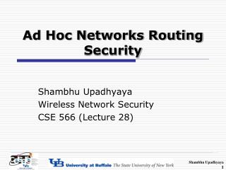
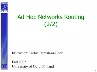
Hop1 Hop3 Hop4 Hop2 <1,2> <1> <1,3,5,7> <1,3,5> <1> <1,3> <1> <1,4,6> <1,4> 7 2 5 1 Source 8 Destination 3 <1,4,6> <1,4,6> 6 4 <1,4,6> Route Discovery in DSR 7 2 5 Source 1 1 Destination 8 3 6 4 4 (a) Building Record Route During Route Discovery (a) Building Record Route During Route Discovery (b) Propagation of Route Reply with the Route Record
AODV supports the use of symmetric channels If a source MH moves, it reinitiates route discovery protocol to find a new route If a MH along the route moves, its upstream neighbor notices the move and propagates a link failure notification message to each of its active upstream neighbors These MHs propagate link failure notification to their upstream neighbors, until the source MH is reached Hello messages can be used to maintain the local connectivity in the form of beacon signals Designed for unicast routing only, and multi-path is not supported Route Discovery in DSR
TORA is a highly adaptive loop-free distributed routing algorithm based on the concept of link reversal TORA minimizes reaction due to topological changes Algorithm tries to localize messages in the neighborhood of changes TORA exhibits multipath routing capability Can be compared with water flowing downhill towards a sink node The height metric is used to model the routing state of the network Nodes maintain routing information to one-hop neighbors Temporarily Ordered Routing Algorithm (TORA)
TORA (Cont’d) Height = 3 Height = 2 Height = 1 Illustration of TORA height metric Source Height = 0 Destination
The protocol performs three basic functions: Route creation Route maintenance Route erasure A separate directed acyclic graph (DAG) is maintained by each node (MH) to every destination Route query propagates through the network till it reaches the destination or an intermediate node containing route to destination This node responds with update and sets its height to a value greater than its neighbors When a route to a destination is no longer valid, it adjusts its height When a node senses a network partition, it sends CLEAR packet to remove invalid routes Nodes periodically send BEACON signals to sense the link status and maintain neighbor list TORA (Cont’d)
2 7 (0,3) (0,1) 5 (0,2) Source Destination 1 3 8 (0,3) (0,3) (0,0) 6 4 (0,1) (0,2) TORA (Cont’d) 2 7 (-,-) (-,-) 5 (-,-) Destination Source 1 3 8 (-,-) (-,-) (0,0) 6 4 (-,-) (-,-) Propagation of the query message Node’s height updated as a result of the update message
The height metric in TORA depends on logical time of a link failure The algorithm assumes all nodes to be synchronized TORA has 5-tuple metric: Logical time of link failure Unique ID of the node that defined the new reference level A reflection indicator bit A propagation ordering parameter Unique ID of the node The first three elements together describe the reference level Oscillation can occur using TORA, similar to count-to-infinity problem TORA is partially reactive and partially proactive TORA Characteristics
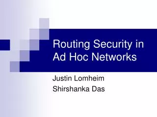
Zone Routing Protocol (ZRP): Hybrid of reactive and proactive protocols Limits the scope of proactive search to the node’s local neighborhood The node need to identify all its neighbors which are one hop away Nodes local neighborhood is defined as a routing zone with a given distance All nodes within hop distance at most d from a node X are said to be in the routing zone of node X All nodes at hop distance exactly dare said to be peripheral nodes of node X’s routing zone Intra-zone routing:Proactively maintain routes to all nodes within the source node’s own zone Inter-zone routing:Use an on-demand protocol (similar to DSR or AODV) to determine routes to outside zone Hybrid Routing Approaches
Zone Routing Protocol (ZRP) Radius of routing zone = 2
Interzone routing protocol (IERP) is responsible Uses a query-response mechanism by exploiting the structure of the routing zone, through a process known as bordercasting Bordercast is more expensive than the broadcast flooding used in other reactive protocols as there are many more border nodes than neighbors Cost of bordercast redundancy reduced by suppressing mechanisms based on query detection, early termination and loopback termination Source generates a route query packet with source node’s ID and request number Sequence of recorded node Ids specifies an accumulated route from the source to the current routing zone If the destination is in routing zone, a route reply is sent back to source, along the path specified by reversing the accumulated route If the destination does not appear in the node’s routing zone, the node bordercasts the query to its peripheral nodes Hybrid Routing Approaches
Fisheye State Routing (FSR): Uses a multi-level Fisheye scopes to reduce routing update overhead in large networks It helps to make a routing protocol scalable by gathering data on the topology, which may be needed soon FSR tries to focus its view on nearby changes by observing them with the highest resolution in time and changes at distant nodes Hybrid Routing Approaches
Landmark Routing (LANMAR) with group mobility: Combines the features of FSR and landmark routing Uses a landmark to keep track of each set of nodes that move together Borrows the notion of landmarks to keep track of logical subnets The MHs exchange the link-state and topological information only with their immediate neighbors It also piggybacks a distance vector with size equal to the number of logical subnets and thus landmark nodes A modified version of FSR used for routing by maintaining routing table within the scope and landmark nodes Hybrid Protocols
Cluster-based Routing (CBRP): This is a partitioning protocol emphasizing support for unidirectional links Each node (MH) maintains two-hop topology information to define clusters Each cluster includes an elected cluster head, with which each member node (MH) has a bi-directional link In addition to exchanging neighbor information for cluster formation, nodes must find and inform their cluster head(s) of status of “gateway” nodes Cluster infrastructure is used to reduce the cost of disseminating the request When a cluster head receives a request, it appends its ID and a list of adjacent clusters and rebroadcasts it Each neighboring node which is a gateway to one of these adjacent clusters unicasts the request to appropriate cluster head Hybrid protocols
Routing protocols that take advantage of location information Can be classified according to how many MHs have the service Forwarding decision by a MH is essentially based on the position of a packet’s destination and the position of the MH’s immediate one-hop neighbor Position Based Routing
Three main packet forwarding schemes: Greedy forwarding Restricted directional flooding Hierarchical approaches For the first two, a MH forwards a given packet to one (greedy forwarding) or more (restricted directional flooding) one-hop neighbors The selection of the neighbor depends on the optimization criteria of the algorithm The third forwarding strategy forms a hierarchy in order to scale to a large number of MHs Position Based Routing
Position Based Routing Classification criteria for existing approaches: +
MHs register their current position with this service When a node does not know the position of a desired communication partner, it contacts the location service and requests that information In classical one-hop cellular network, there are dedicated position servers, with each maintaining position information about all MHs In MANETs, such centralized approach is viable only as an eternal service First, it would be difficult to obtain the location of a position server if the server is a part of the MANET Second, since a MANET is dynamic, it might be difficult to have at least one position server within a given MANET Location Services
Within Distance Routing Effect Algorithm for Mobility (DREAM) framework, each MH maintains a position database that stores the location information about other MHs An entry in the position database includes a MH identifier, the direction of and distance to the MH, as well as a time value when this information has been generated A MH can control the accuracy of its position information available to other MHs in two ways: By changing the frequency at which it sends position updates and is known as temporal resolution By indicating how far a position update may travel before it is discarded which is known as spatial resolution Distance Routing Effect Algorithm for Mobility
Temporal resolution of sending updates is coupled with the mobility rate of a MH, i.e., the higher the speed is, more frequent the updates will be Spatial resolution is used to provide accurate position information in the direct neighborhood of a MH and less accurate information at nodes farther away Costs associated with accurate position information at remote MHs can be reduced since greater the distance separating two MHs is, slower they appear to be moving with respect to each other For example, from MH A’s perspective, the change in direction will be greater for MH B than for MH C A B C C B Distance Effect in DREAM
Information updates (write operations) are sent to a subset (quorum) of available nodes, and information requests (read operations) are referred to a potentially different subset When these subsets are designed such that their intersection is nonempty, it is ensured that an up-to-date version of the sought-after information can always be found A set of MHs is chosen to host position databases Next, a virtual backbone is constructed among the MHs of the subset by utilizing a non-position-based ad hoc routing algorithm A MH sends position update messages to the nearest backbone MH, which then chooses a quorum of backbone MHs to host the position information Quorum-Based Location Service
1 A D 6 2 C B 4 3 5 S Quorum-Based Location Service • MH D sends its updates to node 6, which might then select quorum A with nodes 1, 2, and 6 to host the information • For example, MH 4 might, choose quorum B, consisting of MHs 4, 5, and 6 for the query • Larger the quorum set is, higher the cost for position updates and queries are • Can be configured to operate as all-for-all, all-for-some, or some-for-some approach
Query 78 31 29 25 57 64 10 15 80 48 56 73 14 34 Grid Location Service • Divides the area that contains the MANET into a hierarchy of squares, forming a so called quad tree • Each node maintains a table of all other MHs within the local first-order square • Establishes near MH IDs, defined as the least ID greater than a MH’s own ID • Position information of 10 is available at nodes 15, 18, 73 • Second order squares Nodes 14, 25, and 29 are selected to host the node 10’s position 78 78 36 43 Location update 31 31 29 25 25 57 64 10 10 15 80 80 48 56 18 73 34 14 14 34
Two almost identical location services have been proposed independently Both use the concept of a virtual Homezone where position information for a node is stored By applying a well-known hash function to the node identifier, it is possible to derive the position C of the Homezone for a node All nodes within a disk of radius R centered at C have to maintain position information for the node Homezone
C B S D r A Greedy Packet Forwarding r indicates the maximum transmission range of node S • Sender includes an approximate position of the recipient in the packet • This information is gathered by an appropriate location service • Intermediate node forwards packet to a neighbor lying in the direction of recipient • This process can be repeated until recipient has been reached • A good strategy when sender cannot adjust the transmission signal strength
Greedy Packet Forwarding (Compass Routing) • Forwarding packets in which the neighbor closer to the straight line between sender and destination is selected • It is possible to let the sender randomly select one of the nodes closer to the destination than • Greedy routing may fail to find a path between a sender and a destination, even though one does exist • To counter this problem, the packet should be forwarded to the node withthe least backward (negative) progress • However, this raises the problem of looping D S
A B D C Greedy Perimeter Stateless Routing Protocol • Based on planar graph traversal • Nodes do not have to store any additional information • A packet enters the recovery mode when it arrives at a local maximum • It returns to greedy mode when it reaches a node closer to the destination • The graph formed by a MANET is generally not planar as shown • An edge between two nodes A and B is included in the graph only if the intersection of the two circles with radii equal to the distance between node A and B around those two nodes does not contain any other nodes • The edge between nodes A and C would not be included in the planar subgraph since nodes B and D are contained in the intersection of the circles
D S Planar Graph Traversal • A simple planar graph traversal is used to find a path toward the destination • Forward packet on faces of planar subgraph progressively closer to the destination • On each face from node S toward node D, the packet is forwarded along the interior of the face: forward the packet on the next edge counterclockwise from the edge on which it arrived • Algorithm guarantees that a path will be found in case at least one exists • The header of a packet contains additional information such as the position of the node, the position of the last intersection that caused a face change, and the first edge traversed on the current face
Restricted Directional Flooding • Sender node S of a packet with destination node D forwards the packet to all one-hop neighbors that lie “in the direction of node D” • Expected region is a circle around position of node D as it is known by node S • “Direction towards node D” is defined by the line between nodes S and D and the angle
Location-Aided Routing (LAR) uses position information to enhance the route discovery phase of reactive ad hoc routing approaches LAR uses this position information to restrict the flooding to a certain area called request zone at the time of route discovery If node S knows that node D travels with average speed v, then the expected zone is the circular region of radius v(t1 - t0), centered at location L Expected zone is only an estimate made by node S to determine a region that potentially contains D at time t1 L Expected Zone Routing L v (t1 – t0)