Download

1 / 15
150 likes | 180 Views
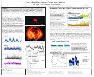
This research paper discusses the three-dimensional density and magnetic structure of Coronal Mass Ejections (CMEs) in the solar corona using polarimetric measurements and LASCO data. It examines two well-observed CME events and explores their angles of emergence, magnetic field direction, and evolution. The paper highlights the importance of understanding CME physics for space weather forecasting and provides insights into CME topology using visualization techniques.

E N D
Three-Dimensional Structure of Coronal Mass Ejections From LASCO Polarization Measurements K. P. Dere, D. Wang and R. Howard ApJL, 620; L119-L122 2005 February 20 2005.02.14 Monday Seminar; Rapid; Taro Morimoto
Abstract Polarimetric measurements with LASCO Three-dimensional structure of a CME. Two particularly well observed events are discussed. • 2002 August 1 CME. A rising arcade of loops. • 2002 August 7 CME. A flux-rope type. The LASCO movie of the 2002 August 1 CME.
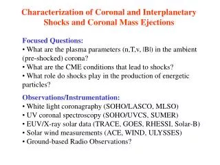
Introduction An understanding of the three-dimensional density and magnetic structure of CMEs in the solar corona is still lacking. • It is very important • from the “space weather” point of view. • for understanding the physics of CMEs. The method described in the papers can provide the information on • The angle at which a CME emerges. • Direction of the magnetic field. • CME shape – spherical shell? expanding loop? • CME evolution. Another CME event on 2002 August 7.
Introduction Previous studies • Poland and Munro 1976 (ApJ, 209; 927-934) 1973 Aug 21 CME & prominence eruption. Composite photographs of He 304 & white-light image. White-light and He 304 images from Skylab. Ha images from SacPeak. They measured the angle of the CME’s leading edge from the plane of the sky, and demonstrated that it was quite different from that of the accompanying prominence. 1441 UT 1313 UT 1511 UT 1615 UT
Introduction 2. Crifo, Picat and Cailloux 1982 (SolPhys, 83, 143-152) 1973, Aug 10 CME. White-light images from Skylab. They performed polarization measurements and found that the CME is more likely to be a bubble-shaped structure, than a loop. Bubble and loop type CME topologies.
Introduction y (North) x (West) 3. Moran and Davila 2004(Science, 305, 66-70) Sun Brightness Side View (z, y) Earth z LASCO movie of the 1998, Oct 31 event. [Ro] Top View (x, z) Topological map (distance from the [x,y] plane 03:56 UT
To measure I, Q, and U, the fraction of linear polarization, p, is given as The polarization brightness is defined as In order to remove the contributions from F-corona and instrumental polarization, “background” polarization and brightness must be subtracted. f : contributions from CME alone b: background (pre CME) Method Thomson Scattering of Radiation The observed radiation of a CME is assumed to be due to scattering from electrons in the CME, thus it becomes polarized. Its polarization fraction depends on the angle of the scattering. .
Observation Weighted average angle (distance) of the scattering plasma from the plane of the sky. Method Calculation The polarization for Thomson scattering as a function of angle (f) from the plane of the sky.
41 CME observations during the period. Especially well observed CMEs on 2002, Aug 1, 2002, Aug 7. Data LASCO C2 data during a special month-long (2002 July – August) campaign “LASCO C2 Polarization Measurement”. • Binning = 2 (512 x 512 sized images; Pixel size = 22.8”) • 1hr cadence. (Exposure time = 100s for each image). • Default wavelength = 550 nm.
When the CME plasma is out of the plane of the sky, the polarization (polarized brightness) become would be reduced. LASCO images of the event at 06:48 UT. Result LASCO C2 movie of the 2002, Aug 1 CME. 2002 August 1 CME.
130 deg rotation. 2. 30 deg rotation. Loop arcade. Result Visualization of the 2002 August 1 CME event.
Result 2002 Aug, 7 CME Can be interpreted as consisting of flux-rope or helical structure. The observation and visualization of the 2002, Aug 7 CME.
The foreground/background ambiguity. • The assumption that the line-of-sight integrated intensity can be placed at a single (x, y, z) point. This is convenient for visualization, but may cause misunderstandings of the topology of a CME. Summary Three-dimensional visualization of CMEs has significant impact on • understanding CME physics • space weather forecast • etc. The polarization technique, STEREO imaging, and spectroscopic techniques can complementary provide mutual measure to view a solar ejection structure.
LASCO data The absolute calibration of C2 = 3 %. The polarization characteristics of the C2 coronagraph is less known. Assumption that the polarizers are ideal is made. There are two flat mirrors on the path of the light.