Download
1 / 34
340 likes | 479 Views
Femoral Fracture Reduction Device. Group 1: Supervisor: Michael Lasaga Dr. Ted Hubbard Andrew Allan Clients: Riley Wilson Dr. Michael Dunbar Xiang Gong Dave Wilson. Presentation Outline. Problems with Current Surgery Design Requirements Final Design

E N D
Femoral FractureReduction Device Group 1: Supervisor: Michael Lasaga Dr. Ted Hubbard Andrew Allan Clients: Riley Wilson Dr. Michael Dunbar Xiang Gong Dave Wilson
Presentation Outline Problems with Current Surgery Design Requirements Final Design Test Procedure and Results Strengths and Weaknesses Final Budget Conclusions and Recommendations Red Line 1 inch
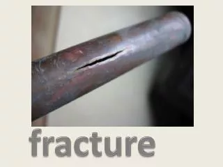
Problem with Current Surgery • Time in the Operating Room • Huge cost • Huge health risk • Difficult Procedure • Only skilled surgeons capable • Possibility for infection • Forces on the Patient • Manual Fracture Reduction
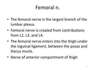
Design Requirements (General) To bridge femoral gap To reduce femoral fracture
Design Requirements (Specific) • Must be able to be sterilized or be disposable • Must fit in medullar canal (avg. diameter of 12mm) • Must be greater than 480 mm in length • Must be able to bend 30 degrees • Must have separate tip control • Must be hollow through center (intermediate wire 2.5mm) • Must be able to apply 75Nm moment about the knee joint
Final Design Concept “Snake Rod” Design
Final Design Components • Tensioning Mechanism • Stainless Steel Wires Proximal Rod Ball Joints
Final Design (Proximal Rod) • Immobile part of device • Stainless steel • 450mm long x 9.5mm diameter • 3.4mm diameter center hole • Required 6 holes to run wires • 6 x 1.25mm diameter holes 10mm deep at each end • 6 slots that extend between these holes • Ball joint at tip
Final Design (Ball Joints) Allow mobility of the device Matching holes compared to proximal rod Each joint has a ball or socket on either end
Final Design (Ball Joints) • Section 1 – 9 large primary joints • Section 2 – 3 small primary joints • Allow better range of motion • Section 3 – 4 small secondary joints • Section 3 controlled independently from 1 and 2
Final Design (End Control) Independent control of secondary joints allows formation of S-shape Allows device to steer across most common fractures
Final Design (Stainless Steel Wiring) • Four wires in total • Two 0.70mm diameter (Black) • Control Primary Joints • Two 0.35mm diameter (Green) • Control Secondary Joints
Final Design (Tensioning Mechanism) • Two C-Channels welded at 120o angle • Wires are counter wrapped onto worm gears • Left worm gear controls primary joints • Right worm gear controls secondary joints • Intuitive Controls • Proximal rod fastened using threaded collar and two nuts
General Testing Procedures Mobility Forces
Testing Procedure (Mobility) Device was passed through femoral canal until a specific number of joints were exposed Range of motion was determined using a protractor Tested range with 4 secondary segments out of Saw Bone Tested range with 3 primary joints out of Saw Bone Tested range with 6 primary joints out of Saw Bone
Testing Procedure (Forces) Used broken Saw Bone to model femur Proximal end of bone clamped to table Distal end of bone mounted so that it can pivot at the knee Distal end of fracture site tied to spring scale Bone is positioned to imitate a typical misalignment Measured forces produced by device in an effort to reduce the fracture
Testing Results (Forces) 7.5lbs of force achieved at the tip
Testing Procedure (Failure) The worm gear failed at low force The worm gear should be redesigned Calculations were done to extrapolate forces of stronger gear
Testing Results (Failure) • Calculated forces needed to fail • 0.7 mm wire: 1144 N • 1.0 mm wire: 2356 N • Worm gear failure occurred at 10 Nm of moment about the knee • Max moment with new wire and worm gear: 43 Nm
Strengths Failure occurs outside of patient instead of inside Sufficient mobility between joints Primary deflection angle can reach 100 degree Perfect S-shape can be created High durability with stainless steel wires and parts
Strengths Ease of manipulation Only two turning controllers Moderate linear-turning speed 30 degree of clearance Cost-$2,300 Large saving on the operation procedure Major cost is the machining spending Multiple use
Weaknesses • Insufficient forces produced at tip • 10 Nm produced in the test, about 15% of moment required about the knee • Inefficiency on wire tying • Counter-wrapping stiff wires • Hard to tie tightly
Conclusions and Recommendations Design meets all requirements other than force Surgeon can apply lacking force Excellent mobility Can be applied for most common fractures Will reduce time and cost in OR Stronger worm gears More practical method of tying wires Should see a tool in the future
Questions? • Group 1 • Michael Lasaga • Andrew Allan • Riley Wilson • Xiang Gong • Supervisor • Dr. Ted Hubbard • Clients • Dr. Michael Dunbar • Dave Wilson • Special thanks to: • Priority Precision • Orthopedic Research Group • Mark • Angus • Albert • Craig