Download
1 / 7
70 likes | 141 Views
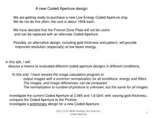
Notes for xBSM meeting, 2012-01-05 Fits for Pinhole and FresnelZonePlate have been standardized to each call the same “TwoGaussFit”. There are 4 free parameters: Beam Size, Position Fraction of Image Area in SIGNAL

E N D
Notes for xBSM meeting, 2012-01-05 Fits for Pinhole and FresnelZonePlate have been standardized to each call the same “TwoGaussFit”. There are 4 free parameters: Beam Size, Position Fraction of Image Area in SIGNAL Fraction of Image Area in Flat Background Each has a “signal” or “line shape” defined by 2 Gaussians, hence 6 fixed parameters : PinHole FresnelZonePlate Narrow Gaussian Locate 0 0 Fraction of SIGNAL 0.8 0.1284 Intrinsic Width 0 † 0.288 pixel =1/sqrt(12) Wide Gaussian Locate 0 0 Fraction of SIGNAL (1-0.8) (1-0.1284) Intrinsic Width 2 pixel 3.925 pixel † (subtracting(quad) 18 microns, 0.9 pixel at the image)
Coded Aperture: Implemented the DanP parameterization of the DanP calculated image from January 2011. The “line shape” is 12 gaussians, 36 fixed parameters. There are, AGAIN, 4 free parameters: Beam Size, Position Fraction of Image Area in SIGNAL Fraction of Image Area in Flat Background Well, OK, there is a 5th free parameter: Background slope, but this is constrained to 0 ± 2% . Also, implemented the DanP parametization of the JohnF calculated image for zero beam size, zero offset, some standard area. ~All information from John’s calculation is in this image. Brian templates in beam size. The MatLab code convolutes the beam size by describing the image as a linear sum of Gaussians.
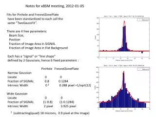
DanP parameterization of the DanP calculated image DanP parameterization of the JohnF calculated image
Study of IBS data taken night of 2011-12-14 Conditions as described: PinHole subtractor: 18 microns CodedAperture: DanP January 2011 Systematic issues: PinHole result will increase with smaller subtractor. CodedAperture result will increase with decreased background level (slide) with decreased Gaussian widths (slide) . Will the agreement remain intact? I don’t know.
Extending to Left and Right sides of Coded Aperture image Fitted beam size in Coded Aperture is highly correlated with the background. Investigate the background level and slope. We did this 2 times: 2011-12-07 004018, 20, 21 2011-12-15 021428, 29, 30 . It could be done more often. Better to analyze this with averaged images. Learn that the background level should be lower, and the background is slightly higher (~4% ?) on the Left, and can be locked.
Intrinsic Gaussian widths: an error from January 2011 (This is kind-of technical.) The parameterization to 12 Gaussians starts with a smoothed image. [smoothed bin value] = (self + ½ NearestNeighbors) /2 This introduces a FWHM of 2 bins (=1 pixel) . A new parameterization matches the smoothed images with an equally smoothed Gaussian parameterization but with reduced intrinsic widths. With a value of 1 in the center, and ½ in the side bins, the RMS of this thing is 2-1/2 bins, or 0.3536 pixel. Optimum was found at 0.3735 pixel, 7.5 micron referred to the source. The line shape was too wide; ADD this subtractor.
Thinking about adding the semi-transparency of the mask. ( JohnF knows all about this. ) Increased the optics integration range beyond the 310 micron height Coded Aperture. 500 microns is still not enough. 500 microns * (projection =3.3) = 1.65 mm This causes those bumps on the sides. We can read off the semi-transparency from slide 5. 50% amplitude transmission (25% intensity) , -0.2λ phase shift ( vphase/c > 1 ) may have some nice features. (BLUE line) deaper central valley , w.r.t. the background level, more defined side peak on main peak. Must install transmission based on observed and phase shift based on material.