Download
1 / 45
450 likes | 564 Views
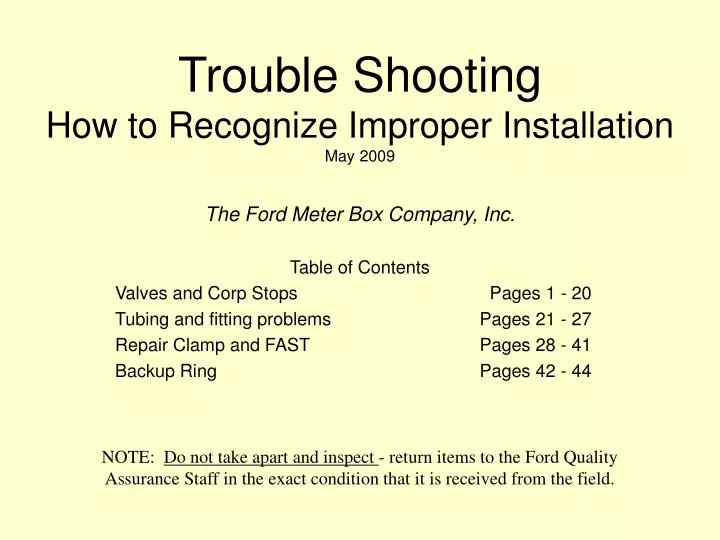
Trouble Shooting How to Recognize Improper Installation May 2009. The Ford Meter Box Company, Inc. Table of Contents Valves and Corp Stops Pages 1 - 20 Tubing and fitting problems Pages 21 - 27 Repair Clamp and FAST Pages 28 - 41 Backup Ring Pages 42 - 44.

E N D
Trouble ShootingHow to Recognize Improper InstallationMay 2009 The Ford Meter Box Company, Inc. Table of Contents Valves and Corp Stops Pages 1 - 20 Tubing and fitting problems Pages 21 - 27 Repair Clamp and FAST Pages 28 - 41 Backup Ring Pages 42 - 44 NOTE: Do not take apart and inspect - return items to the Ford Quality Assurance Staff in the exact condition that it is received from the field.
Leaking valve. Pipe wrench distortions shown on a key style corp stop. View 1 of 2
Why pipe wrenches should not be used. Iron teeth easily distort brass material Increased torque on wrench handle squeezes jaws more tightly against the valve or fitting. Typical pipe wrench jaws are 5 to 7 degrees from parallel
A dye test shows that pipe wrench distortions transferred through body.View 2 of 2 Raised Area
A loose-fitting, smooth-jawed wrench can distort valve body. View 1 of 2
Wrench placement or looseness that caused valve body distortion.
Dye test shows loose wrench distortions transferred through valve body.
Valve leaks at valve body. Pipe wrench distortions break the machined seal between the valve body and the outlet assembly. Outlet assembly Teeth marks from pipe wrench Should locate smooth jaw wrench on the flat area here Valve body
Valve leaks after backfill. A dye test shows a key style corp stop with an arched body. Incorrect! Vertical key placement can distort or “arch” the valve when backfilled No dye = lack of seal because of no key contact Correct! Valve installed on its side will absorb higher backfill force
Valve leaks during pressure test. The grooves (scars) on the key are caused by operating the valve against stones or shavings. This valve was not properly flushed after installation.
The key port is distorted from a drilling operation that was done with the key not completely open.View 1 of 3
The key port is distorted from a drilling operation that was done with the key not completely open.View 2 of 3
The machined surface of a key corp body is scored from turning a distorted key. View 3 of 3
Valve is hard to operate. Ball distortion results from freezing.
Valve leaks / hard to operate. The key is bulged from the expansion of frozen water. The key was in the closed position when frozen. View 1 of 2
Valve leaks / hard to operate. The key is bulged from the expansion of frozen water. The key was in the closed position when frozen. View 2 of 2
Valve appears to be closed but allows water flow. A ball valve not fully closed when the tee-head is in a fully closed position. View 1 of 3
Valve appears to be closed but allows water flow. Note the twisted tee-head spade due to valve operation while frozen. View 2 of 3
Valve appears to be closed but allows water flow. The distortion of the ball slot is the result of operating the valve while frozen. View 3 of 3
Leaking compression fitting. Out-of-round copper tubing can cause a poor gasket seal. View 1 of 2 Copper Rounding Tool 3/4” - CRT-3 1” - CRT-4 1-1/4” - CRT-5 1-1/2” - CRT-6 2” - CRT-7
Leaking compression fitting. Out-of-round copper tube compared to a round fitting. View 2 of 2
Leaks after in service for weeks or months. Deflected copper can cause a poor gasket seal. View 1 of 3
Leaks after weeks or months - deflected / out of round. The narrowing of the shiny band shows an uneven gasket seal. The leak usually occurs at the most narrow part of the shiny area. View 2 of 3
Leak. Classic erosion pattern is from water escaping from between the gasket and the copper. View 3 of 3
Leak. An incomplete insertion of the copper tube into the fitting allows too much deflection. View 1 of 2
Leak. Part of the gasket was compressed over the end of the tube causing a poor gasket seal. View 2 of 2
Equal torque must be applied to all bolts/nuts to prevent leak. The wavy side bar shows over-torque. An over-torque can break the weld between the side bar and the band.
The cupped lifter bar shows proper installation torque. View 1 of 3
The cupped washer shows proper installation torque. View 2 of 3
Displacement of coating shows proper torque on each component. View 3 of 3
Protrusions on the band show that the finger lugs were placed under the band. Most commonly found on the underside of pipe. View 1 of 2
The uniform gasket indentations show that the finger lugs were under the band. View 2 of 2
Leak. The bulge on the band shows that debris was trapped under the clamp.
This repair clamp was used where a coupling should be installed. The indentations on the band show the end of the pipe. See Catalog Section L for proper applications. View 1 of 2
This repair clamp was used as a coupling. The indentations on the band show the end of the pipe. Close-up view of band. View 2 of 2
A repair clamp as a "transition" coupling. View 1 of 3 Additional stress on the band-to-sidebar weld at the pipe diameter transition area PVC pipe side 11.10" (smaller) diameter Cast iron pipe side likely 11.60" (larger) diameter Sidebar
A repair clamp as a "transition" coupling. View 2 of 3 Broken band-to-sidebar weld PVC pipe side 11.10" (smaller) diameter Cast iron pipe side likely 11.60" (larger) diameter
A repair clamp as a "transition" coupling. View 3 of 3 Stud Lubricant Lifter Bar Washer Sidebars Set of finger lugs PVC pipe side Cast iron pipe side
This 3-piece tapping sleeve leaked because the bottom row of bolts was not torqued. During installation, tighten so the torque and gap are equal. This will prevent leaking. Unequal gap - no gap on left, large gap on right and bottom nuts not torqued.
Gasket Failure - not enough bolt torque was applied during installation.
Coupling End RingOver tightening the fasteners may break the casting. View 1 of 3