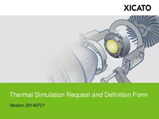
Thermal Simulation Request and Definition Form
Thermal Simulation Request and Definition Form. Version 20121205. Introduction.


Thermal Simulation Request and Definition Form
E N D
Presentation Transcript
Thermal Simulation Request and Definition Form Version 20121205
Introduction One of the most important parts of any analysis, thermal or not, is proper setup and definition. Without clear and precise setup, an analysis can be off by orders of magnitude, with meaningless results. This document will guide you through a step by step process to define the thermal model and associated boundary conditions to ensure accurate results. Throughout this document, there will be places to add text, makes selections, and add pictures. These places will be indicated in YELLOW highlighting or shapes. Please add information as required in the indicated yellow areas by using your mouse to click (or double click) until the text cursor appears, then type in the requested information. When done typing, use the mouse to click elsewhere on the page to finish text entry. Additionally, areas of RED show important notes, reminders, or cautions. Customer Information: Company Name – Company Name Here Requester Name – Requester Name Here Luminaire Name – Luminaire Name Here Date – Date Here Company Name Here To edit text fields, move your mouse cursor over the yellow box and click (or double click) until the text cursor flashes in the yellow box. Delete the existing text then type the necessary information. Finally, use your mouse to click outside of the box to disable text entry Requester Name Here Company Name – Requester Name – Luminaire Name – Date – __________________________ __________________________ __________________________ __________________________ Luminaire Name Here Date Here
Material Definition # Make sure all components have been defined
Material Definition (continued) # Make sure all components have been defined
Interface Definition # *Air gap (1 mil) is equivalent to standard part to part contact, with no thermal interface material in between. **DO NOT specify thermal interface between the module and the heat sink. All XSM, XLM, & XPM ship with eGRAF HT-1205 thermal pad attached and will be used in the analysis. Make sure all interfaces have been defined
Interface Definition (continued) # Make sure all interfaces have been defined
System Definitions – Product Selection Please only select highest drive current required. Multiple selections will delay results. Maximum Thermal Class – ______ *See following slide for corresponding Thermal Class Goal of Analysis – ______________________________________ Maximum Operating Ambient Air Temperature – _______ºC Color of Heat Sink or Primary Thermal Dissipator – ______________ Will the fixture be in-ground or in a sealed cavity? – ______________(if Yes, please fill out details on next page ? Determine Maximum XSM Tc Temperature 40 Black Y/N
Please leave as “N/A” if this doesn’t apply, otherwise delete “N/A” and define cavity size, materials and orientation. In-Ground or Sealed Cavity Definition # # N/A #
Thermal Classes (–C XSM) Thermal Classes also listed in module Data Sheets
Simulation Orientations Legend ### ### 0 Orientation 1 ____ ° Orientation 2 ____ ° Orientation 3 ____ ° 180° 90° 270° 0° j j Gravity 9.81m/s² (1.64m/s² if luminaire installed on moon)
Additional Notes • Submit completed forms to thermal.sim@xicato.com along with exported CAD files. • Simulation results should always be verified by making prototypes and comparing measured temperature values. • Simulation does not qualify under the Xicato Luminaire Validation Program – see program requirements for details. • Simulation results do not guarantee performance or lifetime: results should be used as design guidance only. • Drivers and electronics can be simulated for power dissipation, but due to complexities and accuracy issues with individual temperature (i.e. capacitors, ICs, etc.), temperatures of drivers and electronics will not be accurate and therefore not reported. Electronics temperature gradients shown in thermal plots should be disregarded. • For additional help or information, please contact your Xicato technical representative, or email support@xicato.com.