Download
1 / 42
420 likes | 603 Views
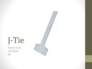
J-Tie. Patrick Jones 5-20-2013 4B. Overview. Introduction Problem Statement Justification Hypothesis Patent Solutions Possible Approaches Design Solution Testing Conclusion Acknowledgements. Introduction.

E N D
J-Tie Patrick Jones 5-20-2013 4B
Overview • Introduction • Problem Statement • Justification • Hypothesis • Patent Solutions • Possible Approaches • Design Solution • Testing • Conclusion • Acknowledgements
Introduction • Every year over one million home units are constructed in the United States (NAHB) • Every year natural disasters damage or destroy thousands of homes • Wind damage caused by coastal hurricanes is one of the largest contributing factors to these losses • Building codes regulate construction (IRC) • Mistakes are still made • Connection mistakes • Could be serious during high wind events • Truss to wall connections are common • Product developed to avoid truss to wall connection mistakes • J-Tie
Problem Statement • Truss tie-downs used for roofs framed with Metal Plate Connected Wood Trusses can be slow and inefficient to install. Sometimes tie-downs are missed by builders, creating dangerous situations for homeowners. Current products do not allow for the tie-downs to be pre-installed by truss manufacturers before the truss is on the roof due to stacking and delivery problems. A device must be created to allow for the pre-installation of truss tie-downs without sacrificing strength, cost, or transportation abilities of a truss. This will ensure that the proper tie-down is installed every time.
Project Focus • Solving the problem of missed or inadequate rafter/truss-to-wall connections - OBJECTIVES • Move installation process to the truss manufacturing plant where tight quality control programs are typically in place and design information is readily available. • Ensure that the required hardware is installed as intended by the truss engineer or building designer • Do not disrupt normal processes • The new product is called the J-Tie • Economicalrafter tie-down solution • Easily be installed in the truss manufacturing plant • No disruption to the normal truss design and delivery process.
Justification • Research to evaluate the need for the product • Industry Surveys • Professional Opinions • Storm Damage Reports
Survey Surveys • A framing contractor survey was conducted to determine if there was a need for this product to be developed. • The survey was conducted in November, 2012 and was distributed to industry personnel using a website portal provided by the Truss Plate Institute. • The following are the questions asked on the survey, and the general response returned:
Question 1 • About 45% of the respondents stated that they “sometimes” install truss tie-downs
Question 2 • About 2/3 of the respondents stated that they typically use a simple “L-shaped” tie-down when required.)
Question 3 • Most of the respondents scored this question indicating that the installation of tie-downs was moderately difficult • No respondent indicated that it was extremely difficult with a 10 ranking
Question 4 • Over1/3 of the respondents felt that the current tie-downs on the market could be improved
Question 5 • The average time to install a tie-down found from this survey was 5-10 minutes
Professional Opinions • Kelly Sias, P.E. – Simpson Strong-Tie, Sun City Arizona “Load path is the key to a wind resistant structure. There must be a continuous and adequate load path from the roof trusses to the foundation”. • David A. Nickle – Wood Fabricators, Inc., Quarryville, PA “We provide tie-down hardware for many of our customers. If the tie-downs were pre-installed, we could ensure that they are put on properly. Right now, we can’t be sure if the tie-downs are even getting installed”. • Mike Walsh, P.E., S.E. – KRW Consulting Group, LLC, Chicago, IL “We specify the exact tie-down hardware to use on our truss drawings. If an installation contractor chooses not to use that hardware, they are taking over the responsibility for the design. It would be good to have the truss manufacturer install the tie-down hardware since they have more control over that part of the process.” • Jay P. Jones, P.E. – Truss Plate Institute, Alexandria, VA “During structural investigations I have observed connection hardware that has been installed improperly that was completely missed by the Building Official during the framing inspection. Having a pre-installed product in a controlled manufacturing plant would solve this problem.” • Harry Kuchma, P.E., S.E. – KRW Consulting Group, LLC, Chicago, IL “If the proper tie-down hardware is not installed, it completely comprises the structural integrity of the building.”
Storm Damage Reports • Hurricane Andrew (by American Plywood Association) • Was a full investigation of damaged homes following storm • Also a Technical Report by Charlie C. Hoover - Alpine Engineered Products • Thought Building Codes were wrong at first • Realized many damages were due to improper construction • LaPlata Tornado Report • Conducted by NAHB Research Center • Also found construction mistakes
Hypothesis • If a new product is developed that will allow for the pre-installation of hurricane-ties, then homes will be more likely to be constructed as specified in the engineering design plans.
Patented Solutions • Number of patents found: 3 • Most recent patents • Truss tie-down method and apparatus - Kevin William Weeks (Patent # 6843028) • Mortise and tenon joint for post and beam I-beams - Harold E. Metzler (Patent # 6272796) • Tie-down strap for building truss - Wayne M. Knoth (Patent # 5561949)
Truss tie-down method and apparatus • Patent Number: 6843028 • Filing Date: Jan 16, 2004 • Award Date: Jan 18, 2005 • Inventor(s) Name: Kevin William Weeks • Inventor(s) Phone: N/A • Inventor(s) Address: Woodcock Washburn LLP One Liberty Place, 46th Floor , 1650 Market Street Philadelphia, PA 19103 (US) • Assignee(s): Weeks Peacock Quality Homes Pty. Ltd. • Class Name/Number: 52/92.2; 52/93.2; 52/639; 52/696; 403/256; 403/345 • Subclass Name/Number: E04C/300; E04B/100; E04B/700 • Product Found In: A tie-down connecting elements for tying down a truss relative to a wall frame is fixed between the webs of the upper and lower Z-shaped chords and includes a tongue portion which extends downwardly through a slot formed in the lower flange of the lower chord of the truss.
Mortise and tenon joint for post and beam I-beams • Patent Number: 6272796 • Filing Date: Dec 30, 1999 • Award Date: Aug 14, 2001 • Inventor(s) Name: Harold E. Metzler • Inventor(s) Phone: N/A • Inventor(s) Address: 107 Oakdale Rd., Martinsburg, PA (US) 16662 • Assignee(s):Brian E. Glessner • Class Name/Number: 52/93.1; 52/93.2; 52/263; 52/283; 52/309.1; 403/245; 403/403 • Subclass Name/Number: E04B 704 • Product Found In: A mortise and tenon joint for I-beam members. The joint includes an I-beam post and an I-beam beam that interlocks with the I-beam post. The I-beam post and the I-beam beam are each made of fiber reinforced pultruded polymer composite. The web of the I-beam post extends past the flanges of the I-beam post so as to form a tenon. The flanges of the I-beam beam have a pair of aligned throughslots so as to form a mortise that snugly receives, and is filled by, the tenon. The tenon has a plurality of throughbores through the pair of opposing faces thereof. The web of the I-beam beam has a plurality of throughbores that are aligned with the plurality of throughbores in the tenon when the tenon is snugly received in the mortise. Bolts extend through first washers, through the plurality of throughbores in the web of the I-beam beam, through the plurality of throughbores in the tenon, through second washers, and threadably engage in nuts so as to maintain the tenon in the mortise.
Tie-down strap for building truss • Patent Number: 5561949 • Filing Date: Oct 7, 1994 • Award Date: Oct 8, 1996 • Inventor(s) Name: Wayne M. Knoth • Inventor(s) Phone: N/A • Inventor(s) Address: Belmont, Mich./Grand Rapids, Mich. • Assignee(s): Universal Forest Products, Inc. • Class Name/Number: 52/92.2; 52/93.1; 52/93.2; 52/643; 52/714; 52/745.16; 52/745.17; 403/232.1 • Subclass Name/Number: E04B 704 • Product Found In: A truss and tie-down strap assembly for use in conventional building structures are shown. The strap provides direct mounting of the truss to the wall studs to provide increased mounting strength for the roof assembly to the side walls of a structure. One leg of the flexible strap is mounted to the truss assembly and the other leg of the flexible strap is mounted to the top plate and stud assembly. The strap is formed of a flexible material such that it can be easily deformed to accommodate different truss structures and side wall configurations. A truss and tie-down strap according to the invention can be preassembled at one location and mounted to the top plate and wall stud assembly at a separate location.
Approaches • Function • Form • Ergonomics • Aesthetics • Ease of Maintenance • Standardization • Durability • Cost
Testing • Constructability Testing • Installation Testing • Fatigue Bending Durability Testing • Uplift Capacity Testing
Data • Constructability Testing • The tests proved that the J-Tie concept was feasible and constructible.
Data • Installation Testing
Data • Fatigue Bending Durability Testing Straps with the same dimensions and steel specifications were used in this testing and were bent into the 90-degree installed position and then back to the flat position repeatedly until the steel fractured.
Data • Uplift Testing
Conclusion • The J-Tie that has been developed in this project has proven to be a sound engineered solution to make truss-to-wall connections for Metal Plate Connected Wood Trusses. The design criterion that was set forth at the beginning of this project has been met and the product performed well in testing. • The use of the J-Tie for truss-to-wall connections should prove to be an innovative solution to a problem that has been ongoing in the truss industry for many years. Using pre-installed hurricane ties could prevent truss failures in the future, reduce costs, and make the use of trusses much safer.
Questions? • Find more information on J-Tie Website • http://jtie.weebly.com
Acknowledgements • Mentors • Mike Walsh • Kelly Sias • Dave Nickle • Family • Teachers • Classmates