Download
1 / 41
410 likes | 604 Views
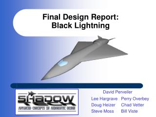
Final Report on LOW Design. Maximizing Science While Minimizing Single Point Failure. Team Eclipse. Project Management. Team Objectives. Develop Teamwork Work as a team in an engineering environment Systems Integration Time management Develop communication skills. Final Concept Drawing.

E N D
Final Report on LOW Design Maximizing Science While Minimizing Single Point Failure Team Eclipse
Team Objectives • Develop Teamwork • Work as a team in an engineering environment • Systems Integration • Time management • Develop communication skills
CDD Requirements • Atlas V-401 EPF with landed mass of 997.4 kg • Propulsion system dry mass is 64.6 kg • First mission at polar location • Capability to land at other lunar locations • Minimize Cost • Launch Date is Sept. 30, 2012 • Capability to move on lunar surface • Survive for 1 year on the lunar surface • Survive the proposed concept of operations • Must meet SMD and ESMD objectives • Land within a precision of ± 100m 3σ • Provide guidance, navigation, and control beginning at 5 km above lunar surface • Capable of landing at a slope of 12 degrees • Designed for G-loads during lunar landing • Design to withstand g-loads with respect to stiffness only
Payload Subsystem Isometric View of LOW • Stereo Imaging • Belly Cam • GN&C
Payload Subsystem • Upon landing, the LOW prepares for single-site goals and multi-site goals. • A drop-box is prepared for single-site goals utilizing various instruments measuring the following parameters: • Lighting conditions • Micrometeorite flux • Electrostatic dust levitation conditions • Meets CDD Single Site Goals • The LOW’s stereo imaging systems’ mast will permanently raise itself to its functional position.
Payload Subsystem • At each site starting at site one, scientific equipment will perform multi-site goals utilizing various instruments performing the following operations: • Regolith sample collection • Geotechnical properties • Regolith composition • Geological characterization • Magnetic susceptibility • Surface temperatures • Alpha particle and gamma ray emissions • Image acquisition • Meets and exceeds CDD Multi-site instrument package goals • Maximized scientific equipment by allotting 325 kg to Payload • 32 Individual pieces of equipment
Payload Subsystem Top View of Payload Layout
Payload Subsystem • Sample Return Vehicle • Utilizes liquid propellant • NTO / MMH • Separate GN&C system • 2 Ring Laser Gyros • Pressure Sensors • Air Speed Sensors • Angle of Attack Sensors • Launches directly from LOW • Site of Launch: Shackleton Crater
At the final site (Shackleton Crater), the SRV will be ready to launch. An arm will load the SRV with regolith samples collected during the course of the mission. Payload Subsystem
Structures Subsystem • 5 G’s Maximum • Semi – Hard Landing Utilizing Crush Pads • Adapted from Mars Viking Lander • Experiences impact velocity of 8 m / s • Minimum Factor of Safety of 1.5 • Verified by Von Mises Stress Criterion • Four Leg Configuration
Structures Subsystem • Landing Phase • Four Unloading Ramps • Primary System • Explosive Bolts • Secondary System • Robotic Arm Assist
Guidance, Navigation, & Control Subsystem • Descent (Terminal Descent Phase – TDP) • Attitude Controllers (ACS) • IMU (Northrop Grumman LN-200 Fiber Optic) • Star Tracker (Goodrich HD-1003) • Sun Sensors (Optical Energy Technology Model 0.5) • Radar Altimeter (Honeywell HG8500) • Actuators • Thrusters/Main Engine (AeroJet MR-106 and MR-80B) • Reaction Wheels (Ithaco Type-A) • Optical (OSS) • DSMAC (Digital Scene Matching Area Correlator) • LiDAR (Light Detection and Ranging) (MDA-Optech) • Guidance Computer (BAE Systems RAD750)
Guidance, Navigation, & Control Subsystem • Experimentation and Traveling (Lunar Excursion Phase – LEP) • 2 Panoramic Cameras (PanCams) • 4 Hazard Cameras (HazCams) • 1 Navigational Camera (NavCam) • 1 Belly Camera (BellyCam) • Also uses the IMU, Tilt Sensors, and the Guidance Computer
Thermal Subsystem • To account for the diverse temperature range (50K – 400K) of the moon, the LOW utilizes a active thermal system with the following components: • Radiators • Heaters • Heat Pipes • Multi – Layer Insulation (MLI)
Power Subsystem • Use of Nuclear Power was avoided • Nuclear power conflicts with the 2012 launch • Requires a 5 year lead time • Pu-238 is scarce
Power Subsystem • Power Source • Solar Arrays • Area of 2.217m2 • Silicon • Mass of 18.203 kg • Solar Power Required 455 We • Power Storage • Lithium Ion Batteries • 24 Batteries • Mass of 9.824 kg per battery • 45 kWe-hr Capacity • During the Dark • 8 days of power at 200 We average • 6 days of sleep phase at 20 We
Communications Subsystem • LOW uses S-band transmitters for communication • Relays data through LRO to Earth at DLS • Relays data to Earth at DLS • Data transfer occurs after each site • Requires approximately 5.5 days to transfer 300 MB of experimental data for each site • DLS of LRO for approximately 8.5 minutes per orbit • Orbit Time of 113 minutes • Data Rate of 72000 bits per second (bps)
Communications Subsystem • Communication and Data • Gives and receives telemetry data when in LOS to LRO and Earth • Stores all data on 2 different 32 GB non-volatile memory • Has no moving parts • Redundancy
SRV GN&C • Control of the rocket • Control in pitch & yaw • 2 actuators • Sensor: 1 IMU • Control of the re-entry capsule • Control on 3 axis • 6 thrusters • Sensor: 1 IMU 3 pressure sensors on the heat shield Actuator Nozzle
Conclusion • Maximize Scientific Payload • LOW has the potential to visit extra sites • LOW can perform more in-depth experiments • Minimize Single Point Failure • Comprised mostly of TRL 9 technology • Conservative ConOps Schedule • No lag time in data communication • Complete Redundancy in GN&C
Landing Landing Phase Battery Power GN&C Landing Legs 1st day Initializing Initializing Phase Com. Sys. “OK” Solar Power Science Box Cameras on 1st day 1st Science Site Science Phase Experiments Com. Phase Data Transfer 1 day Landing Site
Travel to Site Traveling Phase Mobility Solar Power Charge Batteries Com. Phase Data Transfer 4 days Repeat for Light Science Site Science Phase Experiments Com. Phase Data Transfer 1 day Light Sites
Travel to Dark Traveling Phase Mobility Battery Power 4 days Science Site Science Phase Experiments Com. Phase Data Transfer 1 day Repeat for Dark Travel to Light Traveling Phase Mobility Battery Power Com. Phase Data Transfer 3 days Await Sunlight Sleep Phase Minimal Thermal And power 3 days Dark Sites
Travel to EoM Traveling Phase Mobility Battery Power Solar Power 3 Weeks Shackleton Science Phase Experiments Com. Phase Data Transfer EoM & SRV Phase Launch SRV Shackleton Crater