Download

1 / 81
1.58k likes | 2.69k Views
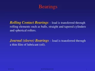
Lubricated and Journal Bearings. Professor John J. Mills Department of Mechanical and Aerospace Engineering The University of Texas at Arlington. Professor John J. Mills: Email: jmills@mae.uta.edu; Tel (817) 272-7366. Outline. General comments about lubricated bearings Lubrication

E N D
Lubricated and Journal Bearings Professor John J. Mills Department of Mechanical and Aerospace Engineering The University of Texas at Arlington Professor John J. Mills: Email: jmills@mae.uta.edu; Tel (817) 272-7366
Outline • General comments about lubricated bearings • Lubrication • Viscosity • Journal bearing design • Reynold’s equation • Long bearing solution (Sommerfeld) • Short bearing solution (Ocvirk and DuBois) • Numerical solution Raimondi and Boyd) • The Norton/Ocvirk approach • Problems with this approach Professor John J. Mills: Email: jmills@mae.uta.edu; Tel (817) 272-7366
Lubricated Bearings • A complex subject • A confusing subject • Multiple approaches • Different sets of assumptions • Different levels of detail Professor John J. Mills: Email: jmills@mae.uta.edu; Tel (817) 272-7366
Before Roller Bearings • The simple lubricated bearing for a wheel and and axle • Around since the invention of the wheel • Problem • Carry a load over rough territory • Solution • The wheel and axle • A revolute pair or joint • Contains a journal bushing pair • Many contexts • Still a powerful solution to many problems Professor John J. Mills: Email: jmills@mae.uta.edu; Tel (817) 272-7366
Comparison to Roller Bearings • Roller bearing advantages over journals • Can support both radial and thrust loads • Are less sensitive to interruptions of lubrication • Have • Low starting and good operating friction • No self excited instabilities • Good low temperature starting • Can seal lubricant within bearing – lifetime lubrication • Typically require less space in axial direction Professor John J. Mills: Email: jmills@mae.uta.edu; Tel (817) 272-7366
Comparison to Roller Bearings • Roller bearing disadvantages over journal bearings • Roller bearings • May eventually fail from fatigue • Require more space in the radial direction • Have • Poor damping ability • Higher noise level • More severe alignment requirements • Higher cost • Higher friction Professor John J. Mills: Email: jmills@mae.uta.edu; Tel (817) 272-7366
Definition of a Journal Bearing • Consists of a rotatable shaft contained within a close fitting cylindrical sleeve • Rotatable shaft is the journal • The cylindrical sleeve is the bearing • The journal and the bearing are separated by a thin film of lubricant • The separation of the two surfaces (the clearance) has four functions • to permit assembly of the journal and bearing • to provide space for the lubricant, • to accommodate unavoidable thermal expansions • to tolerate any misalignments Professor John J. Mills: Email: jmills@mae.uta.edu; Tel (817) 272-7366
Purpose of the Journal/bushing Pair • To allow relative rotary motion • To constrain the nature of that motion Professor John J. Mills: Email: jmills@mae.uta.edu; Tel (817) 272-7366
Key Component of the Wheel and Axle • Lubrication • Otherwise there would be no relative rotary motion • An immense topic in its own right • A true cross-disciplinary research area • Mechanics • Chemistry • Surface physics • Rheology • Fluid mechanics • heat transfer Professor John J. Mills: Email: jmills@mae.uta.edu; Tel (817) 272-7366
Objective of Lubrication • Reduce • Friction • Heating of rubbing/sliding machine parts • Wear Professor John J. Mills: Email: jmills@mae.uta.edu; Tel (817) 272-7366
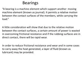
A Lubricant - a Definition • Is any substance which, when introduced between two surfaces moving relative to each other, accomplishes the objectives of lubrication Professor John J. Mills: Email: jmills@mae.uta.edu; Tel (817) 272-7366
Types of lubrication • Five distinct forms of lubrication may be identified: 1 Hydrodynamic 2 Hydrostatic 3 Elastohydrodynamic 4 Boundary 5 Solid-film Professor John J. Mills: Email: jmills@mae.uta.edu; Tel (817) 272-7366
Hydrodynamic Lubrication • Also called • Full film • Fluid lubrication • The load bearing surfaces are separated by a relatively thick layer of lubricant • Prevents metal to metal contact • Stability determined by the laws of fluid mechanics Professor John J. Mills: Email: jmills@mae.uta.edu; Tel (817) 272-7366
Hydrodynamic Lubrication • Requires an adequate supply at all times • Does not require the lubricant to be supplied under pressure • Requires a relative motion between the two surfaces • The lubricant is pulled into the gap between the surfaces by their relative velocity • If the velocity is sufficiently high • A wedge shape film is created that supports the load • The film separates the two surfaces Professor John J. Mills: Email: jmills@mae.uta.edu; Tel (817) 272-7366
Hydrodynamic Lubrication • On start up of the bearing • The journal pumps lubricant under itself • The load is then born by the lubricant which is under pressure created by the pumping action Professor John J. Mills: Email: jmills@mae.uta.edu; Tel (817) 272-7366
Hydrostatic • Occurs when the lubricant is introduced into the gap between the surfaces at a pressure high enough to separate the surfaces • Does not require a relative motion of the surfaces • Not dealt with in this book • Can be important for • Bearings with low or zero velocity • Absolute mimimal friction Professor John J. Mills: Email: jmills@mae.uta.edu; Tel (817) 272-7366
Elastohydrodynamic • Occurs when a lubricant is introduces between two surfaces which are in rolling contact • rolling bearings • mating gears Professor John J. Mills: Email: jmills@mae.uta.edu; Tel (817) 272-7366
Boundary • Occurs when one of the previous mechanism is not valid or fails • The highest asperities of the surfaces are separated by only a few molecules of the lubricant • Mostly chemical in nature • Depends on the nature of the surfaces • Like • Unlike • The change from another mechanism to Boundary is not abrupt Professor John J. Mills: Email: jmills@mae.uta.edu; Tel (817) 272-7366
Comparison of Boundary and Hydrodynamic Coefficient of Friction Boundary mixed hydrodynamic mN/P Professor John J. Mills: Email: jmills@mae.uta.edu; Tel (817) 272-7366
Solid-film • Occurs when a solid film • such as graphite or Molydenum disulphide is used to separate the surfaces • or a plastic like nylon or Teflon forms one of the surfaces • Mostly used for high temperatures Professor John J. Mills: Email: jmills@mae.uta.edu; Tel (817) 272-7366
Combinations of Lubrication • Some systems operate with more than one lubrication type • Elastohydrodynamic • Mixed • Boundary Professor John J. Mills: Email: jmills@mae.uta.edu; Tel (817) 272-7366
Stable Lubrication • Graph from actual test data • Right of AB, lubrication stable • Variations self correcting • The the left of AB, lubrication unstable Professor John J. Mills: Email: jmills@mae.uta.edu; Tel (817) 272-7366
Condition for Stable Lubrication • Units are reyn, rev/s and psi • For centipoise, rev/min and psi, the number is 30 Professor John J. Mills: Email: jmills@mae.uta.edu; Tel (817) 272-7366
Key Factor in Most Lubrication • A key factor in all except solid film lubrication is the viscosity of the medium placed between the surfaces Professor John J. Mills: Email: jmills@mae.uta.edu; Tel (817) 272-7366
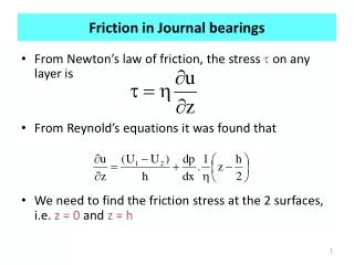
Viscosity • Let a plate A be moving with velocity U on a film of lubricant with thickness h • Imagine the lubricant is made up of layers and the force F moving the plate cases them to slide over each other like a pack of cards Professor John J. Mills: Email: jmills@mae.uta.edu; Tel (817) 272-7366
Viscosity • The Newton's law of viscous effect says that • Where m is the constant of proportionality • The absolute or dynamic viscosity • If the rate of shear is constant, then Professor John J. Mills: Email: jmills@mae.uta.edu; Tel (817) 272-7366
Units for Viscosity • SI units • Pascal-second or Newton-second/square meter • inch pound second (ips) system • Reyn • pound-force-second/square inch • Named after Sir Osborne Reynolds • centimeter gram second (cgs) system • Poise • dyne-second/square centimeter • Not an official ASME unit but still used extensively • Centipoise (0.01 poise) is a convenient number in lubrication Professor John J. Mills: Email: jmills@mae.uta.edu; Tel (817) 272-7366
Units for Viscosity • ASTM standard • Saybolt Universal Viscosity • the length of time it takes for 60 ml of the fluid at a specified temperature to run through a tube 17.6 mm in diameter and 12.25 mm long • kinematic viscosity • unit is the stoke and is in square centimeters/ second • based on fluid flow through tubes • One can convert between any of these with the appropriate equation Professor John J. Mills: Email: jmills@mae.uta.edu; Tel (817) 272-7366
Different Ways of Measuring Viscosity • Rotating • disc • cup • cone • Flow through a tube • Saybolt method Professor John J. Mills: Email: jmills@mae.uta.edu; Tel (817) 272-7366
Viscosity Examples • Viscosities of various lubricants 1 reyn is 1.4 10-7 poise Professor John J. Mills: Email: jmills@mae.uta.edu; Tel (817) 272-7366
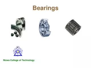
A Journal Bearing • A journal bearing is simply a shaft with a special special bushing surrounding it Bearing Lubricant Journal Professor John J. Mills: Email: jmills@mae.uta.edu; Tel (817) 272-7366
Types of Journal Bearings • Three basic types • Non-self contained • Full bearing • The bearing fully encloses the journal • Partial Bearing • The bearing only partially supports the journal • Self contained • No sump for oil • Pressure fed • Oil is fed under pressure to bearing Professor John J. Mills: Email: jmills@mae.uta.edu; Tel (817) 272-7366
How Design for Journal Bearings • Given information • After designing gears or other devices • Forces and speed • After designing shaft • Shaft diameter • Sometimes • the viscosity of the lubricant • The operating temperature Professor John J. Mills: Email: jmills@mae.uta.edu; Tel (817) 272-7366
How Design for Journal Bearings • Need to specify • Bearing length • Length to diameter ratio • Bearing materials • Clearance ratio • Lubricant viscosity • Sometimes specified by customer • Minimum film thickness • Power loss and hence operating temperature • Ocvirk/Sommerfeld Number • Need theory and observed results • Design with multiple unknowns Professor John J. Mills: Email: jmills@mae.uta.edu; Tel (817) 272-7366
How Design for Journal Bearings • Some guidelines available • Trumpler’s criteria • He was a leading designer several decades ago Professor John J. Mills: Email: jmills@mae.uta.edu; Tel (817) 272-7366
How Design for Journal Bearings • Strategy • Start with length • Relatively insensitive • Estimate the clearance • Determine the viscosity of the lubricant needed to support the load • Assume some operating temperature • Calculate the power loss due to friction • Estimate the temperature rise of the lubricant • Calculate the heat loss in the gearbox and hence the average oil temperature • Redetermine the oil viscosity and iterate Professor John J. Mills: Email: jmills@mae.uta.edu; Tel (817) 272-7366
How Design for Journal Bearings • Calculations not simple! • Theory and experiment in reasonable agreement • No simple analytical equations • We use dimensionless numbers and lots of charts • Just the tip of the iceberg!! • Start with some definitions Professor John J. Mills: Email: jmills@mae.uta.edu; Tel (817) 272-7366
Bearing Length • The length of the bearing on the shaft, l • Film thickness, h Professor John J. Mills: Email: jmills@mae.uta.edu; Tel (817) 272-7366
Bearing Length • The length of the bearing, l, is determined from the load • BUT • Other considerations are dominant Professor John J. Mills: Email: jmills@mae.uta.edu; Tel (817) 272-7366
Bearing Length • Long bearing lengths have a different analysis than short bearings • Long bearings are often precluded by packaging concerns • Not enough space on shaft • Limit shaft deflection Professor John J. Mills: Email: jmills@mae.uta.edu; Tel (817) 272-7366
Bearing Length • Long bearing lengths have a different analysis than short bearings • Long bearings • Are often precluded by packaging concerns • Not enough space on shaft • Limit shaft deflection • BUT • Give lower film pressures • Support larger loads • Necessary when alignment is critical Professor John J. Mills: Email: jmills@mae.uta.edu; Tel (817) 272-7366
Clearance • Various definitions • Radial clearance, cr • The difference in the radius of the shaft and the bearing • Diametric clearance, cd • The difference in the two diameters • Film thickness for an unloaded bearing, h = cd/2 Professor John J. Mills: Email: jmills@mae.uta.edu; Tel (817) 272-7366
Clearance • When the shaft is loaded, the clearance is not the same all the way around the circumference Professor John J. Mills: Email: jmills@mae.uta.edu; Tel (817) 272-7366
Clearance • The film thickness is thus a function of location • Note that the minimum is not directly under the point of application of load Professor John J. Mills: Email: jmills@mae.uta.edu; Tel (817) 272-7366
Clearance • The eccentricity e is the distance between the center of the shaft and that of the bearing • Maximum value is cr • Define a dimensionless eccentricity, e • e = e/cr • This varies from 0 at no load to 1 when the shaft is forced to touch the bearing by a load P Professor John J. Mills: Email: jmills@mae.uta.edu; Tel (817) 272-7366
Other Terms • Radial clearance, cr • The bearing radius - the journal radius • Diametral Clearance, cd • The bearing diameter – the journal diameter • The minimum film thickness, ho, is given by • c = ho+efrom geometry • 1= ho/c+e/c = ho/c+e • e= 1- ho/c Professor John J. Mills: Email: jmills@mae.uta.edu; Tel (817) 272-7366
Clearance and Fluid Pressure • Approximately, the film thickness is given by: Professor John J. Mills: Email: jmills@mae.uta.edu; Tel (817) 272-7366
Clearance Design Principle • We are designing the bearing to ensure that the minimum film thickness under load has an adequate safety factor • The journal does not touch the bearing in operation • Clearance ratio • Fluid viscosity • Surface roughness • The journal is supported by the fluid pressure underthe journal Professor John J. Mills: Email: jmills@mae.uta.edu; Tel (817) 272-7366
Clearance • Clearance is important because • If it is too small • Inadequate lubrication flow • Temperature rises • Bearing may overheat • Minimum film thickness may become too small • Journal rubs on bearing • Design to shaded area Professor John J. Mills: Email: jmills@mae.uta.edu; Tel (817) 272-7366
Clearance • Clearance is important because • If it is too large • Minimum film thickness becomes small again • Shaft “rattles” in bearing • High noise • Design to shaded area Professor John J. Mills: Email: jmills@mae.uta.edu; Tel (817) 272-7366