Download

1 / 31
310 likes | 444 Views
Study of an HHG-Seeded Harmonic Cascade FEL for the UK’s New Light Source Project. Neil Thompson , ASTeC/STFC Daresbury Laboratory

E N D
Study of an HHG-Seeded Harmonic Cascade FEL for the UK’s New Light Source Project Neil Thompson, ASTeC/STFC Daresbury Laboratory On behalf of the NLS FEL Working Group: Riccardo Bartolini (DLS), Jim Clarke (ASTeC/STFC), David Dunning (ASTeC/STFC), Brian McNeil (Strathclyde), Richard Walker (DLS)
Talk Outline • What is the New Light Source (NLS)? • NLS output specification • Design options for FEL: • Laser Seeded HGHG Cascade vs HHG Seeded Cascade • Performance @1000eV • Genesis 1.3 steady-state simulations • Genesis 1.3 time-dependent results • For ideal and S2E bunches, with/without laser heater • Coherence, contrast ratio, pulse length • Summary of output at other photon energies
What is the NLS? • The New Light Source (NLS) project • was launched in April 2008 by the UK Science and Technology Facilities Council (STFC) • The aim is to consider the scientific case and develop a conceptual design for a possible next generation light source based on combination of synchronised conventional laser and FEL sources. • Phase 1 • broad based consultation on science (involving ~300 individuals) to identify science drivers for a new UK light source with unique capability. • Phase 2 • Where we are now. The aim is to produce a facility Conceptual Design Report (CDR) • Have just completed an Outline Design Report (ODR)
Require seeded FEL(s) Need beam energy ~2.25GeV and variably polarising undulators NLS Output Specification • From NLS Science Case: • High brightness coherent light source coverage from THz to 1keV (1.24nm) • Smooth tuning across spectral range • Pulse durations ~20 fs • High degree of transverse coherence • High degree of temporal coherence • Pulse reproducibility After further two-way discussion between FEL group and Science Coordinators: • The full tuning range of the FELs should be 50 eV to 1 keV. The suggested split is into 3 FELs: • FEL-1: 50-300 eV • FEL-2: 250-850 eV • FEL-3: 430-1000 eV • Polarisation Control Required
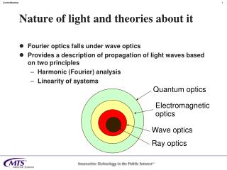
General FEL Landscape Choice for NLS is Laser Seeded HGHG Cascade or HHG Seeded Cascade.
NLS Option 1: Laser Seeded HGHG Cascade FEL High Power Laser @250nm e- FEL @1.25nm MODULATOR CHICANE RADIATOR FRESH BUNCH CHICANE Coherent burst at λlaser/h1due to prebunching Initial quadratic growth Then exponential growth until radiation power sufficient to seed next stage Exponential growth in radiator has induced large energy spread Chicane delays electron bunch so that in next stage radiation seed interacts with fresh electrons Large Energy Modulation Density Modulation with Fourier components at higher harmonics Output from radiator at λlaser/h1 used as new radiation seed for next stage
Option 2: HHG Seeded Cascade FEL High Power IR Laser Gas Cell Low Power HHG Seed @ 12.4nm FEL @1.25nm e- LONGER MODULATOR CHICANE 2nd MODULATOR RADIATOR Modulator 2 short: only long enough to develop enough harmonic bunching at λHHG/h1h2 Chicane only used to optimise bunching, not generate it Initial coherent burst at λHHG/h1h2 which dominates SASE Because the radiation power was never allowed to grow near to its saturation value within modulators, the energy spread growth is modest, so field grows exponentially . No need for a fresh bunch chicane. High gain FEL interaction amplifies seed, giving density modulation with higher harmonic components in modulator itself Small Energy Modulation at start, due to lower seed power Such a scheme proposed by University of Wisconsin: the WiFEL
Shot noise power (W) Seed Power Requirement for each Scheme • For temporal coherence of seed to be retained in FEL, seed power must dominate shot noise power • For direct seeding need approximately Pseed>100×Prad(0) • In harmonic schemes, need Pseed>100×n2×Prad (0) • n is total harmonic ratio between seed and final output. Extra n2 term due to signal to noise degradation in harmonic schemes (Saldin et al) What does this mean for our two options? 35W 12.4nm 250nm 2.7W
HGHG Cascade vs HHG Cascade Laser e- HHG Seeded Cascade FEL Laser Seeded HGHG Cascade HHG Seed Laser Gas Cell e- KEY Bunching Chicane Modulator Radiator Fresh Bunch Chicane
Choice made for NLS Design Study We chose the HHG Seeded Harmonic Cascade FEL • More simpler: fewer components, fewer stages • “Keep it simple!” – Brian McNeil • Appropriate HHG source available within timescale of Project • HHG expertise available within NLS Project: • Imperial College and Central Laser Facility at RAL
Genesis Steady State: FEL-3 @1000eV FEL3 Modulator 2 Modulator 1 APPLE-II Radiator 400kW HHG 100eV e- To allow exponential growth in radiator To allow strong bunching at nth harmonic To give strong coherent burst Modulator 1: Resonant @ 100eV Modulator 2: Resonant @ 200eV Radiator: Resonant @ 1000eV Psat ~1.5 GW Power @ 100eV Power @ 200eV Power @ 1000eV bunching @ 1000eV bunching @ 200eV bunching @ 1000eV
Time Dependent FEL-3 @ 1000eV: Ideal bunch Power @18.7m Spectrum @18.7m Power @18.7m ∆z≈2μm(≈7 fs) ∆λ/λ≈3e-4 Radiation phase @18.7m Power @18.7m ×50 Time-bandwidth product ≈ 0.5 Contrast ratio ≈ 50
Time Dependent FEL-3 @ 1000eV: S2E bunch Spectrum @16.1m Power @16.1m Effect of Laser Heater Spiky Current Profile!
Time Dependent FEL-3 @ 1000eV: Laser Heated S2E bunch Power @19.3m Spectrum @19.3m ∆z≈3.2μm(≈11fs) ∆λ/λ≈4e-4 Contrast ratio ≈ 40 Power @19.3m ×40 Time-bandwidth product ≈ 1
Seeded FELs Layout Modulator 2λw = 44 mm Modulator 1λw = 44 mm APPLE-II Radiatorλw = 32.2 mm FEL3 400kW HHG 75-100eV e- @ 2.25 GeV 20fs FEL Pulse430 - 1000eV Modulator 2λw = 44 mm APPLE-II Radiatorλw = 38.6 mm Modulator 1λw = 44 mm FEL2 400kW HHG 75-100eV e- @ 2.25 GeV 20fs FEL Pulse250-850eV APPLE-II Radiatorλw = 56.2 mm Modulatorλw = 49 mm FEL1 400kW HHG 50-100eV e- @ 2.25 GeV 20fs FEL Pulse50-300eV • All undulator modules 2.5m long • Gaps between modules 1.0m
Conclusion • Design has been developed for HHG seeded harmonic cascade FELs to meet the source requirements of the NLS • Full S2E simulations from Gun to FEL indicate • Good Temporal coherence: time-bandwidth product ≤1 • Short pulses: 11fs @ 1000eV • Ongoing Work • Wakefields • See Jim Clarke’s talk tomorrow THOA03 • Tolerance studies • S2E with error bunches to determine jitter in output properties. • Full S2E at selection of different photon energies to update output predictions for users
Further Information • NLS Project: Science Case and Outline Facility Design published July 2009 • Available from www.newlightsource.org • Other NLS FEL09 Contributions • WEOB02 Optimisation of a single-pass superconducting linac as a FEL driver for the NLS project: Riccardo Bartolini • THOA03 Selection Of The Optimum Undulator Parameters For The NLS: A Holistic Approach:Jim Clarke • FROA04 Timing and Synchronisation Considerations for the NLS Project: Graeme Hirst • TUPC41 VHF High Repetition Rate Photoinjector Design For The NLS Project: Julian McKenzie • WEPC18 A Soft x-ray monochromator for the UK New Light Source (NLS): Mark Roper • WEPC59 Single spike operation for the generation of sub-fs pulses in the NLS: Riccardo Bartolini
The End Thanks for Listening
Tapering • 1st investigations of power enhancement by applying a taper to the radiator undulator. • The taper starts before saturation, and the aw parameter decreases linearly so that as the electron beam energy drops the electrons remain resonant at the FEL wavelength • Optimisation purely empirical for now, although start of taper chosen to be point where beam energy starts to change rapidly: ~20m along radiator for FEL-3 at 1000eV. • In practice the linear taper could be approximated by a module-to-module step taper which could be applied and optimised during FEL operation
Results for FEL-3 Radiator @ 1000eV With taper: ~2.5GW Taper from 20m Without taper: ~1.5GW
NLS Architectural Layout Injector Hall FEL Hall Ancilliary Building: Cryoplant & Services Experimental Hall
Seed Tuning Range + Harmonic Upconversions • n is total harmonic ratio between seed and output. • For 2 conversions, with ratios h1 =[1,2,3,4,5…] and h2 =[2,3,4,5,…], the total harmonic number must be n =h1*h2= [2,3,4,5,6,8,9,10,12…..] • We prefer that h1≤h2 (because bunching is stronger at lower harmonics, and this keeps Modulator 1 as short as possible to minimises energy spread growth before first harmonic upconversion.)
Time Dependent FEL-1 @ 100eV: Ideal bunch Power @16.9m Spectrum @16.9m Power @16.9m ×730 ∆z≈9.5μm(≈30fs) ∆λ/λ≈8e-4 Contrast ratio ≈ 730 Time-bandwidth product ≈ 0.6