Download

1 / 27
270 likes | 443 Views
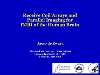
Receive Coil Arrays and Parallel Imaging for fMRI of the Human Brain. Jacco de Zwart. Advanced MRI section, LFMI, NINDS National Institutes of Health Bethesda, MD, USA. Outline. Part I - Receive Coil Arrays Part II - Parallel Imaging Part III - Parallel Imaging & fMRI.

E N D
Receive Coil Arrays and Parallel Imaging for fMRI of the Human Brain Jacco de Zwart Advanced MRI section, LFMI, NINDS National Institutes of Health Bethesda, MD, USA
Outline • Part I - Receive Coil Arrays • Part II - Parallel Imaging • Part III - Parallel Imaging & fMRI
Multi-Coil Imaging ≠ Parallel Imaging?!? • "Parallel Imaging" = multi-coil imaging where data are undersampled during acquisition • Will be discussed in Part II of this talk • Parallel Imaging (PI) requires a receive coil array • Typically results in a loss of SNR compared to the equivalent fully sampled case when using the same hardware • Receive coil arrays used without PI • Covered here in Part I of this talk • Generally yields an SNR increase compared to a conventional volume coil
Why Use a Receive Coil Array? • Smaller coils 'see' less noise increased SNR close to the coil • BUT: small coils have a limited field-of-view • SOLUTION: cover the object with small coils • SNR in center same as with equally-sized volume coil (e.g. birdcage) • SNR everywhere else , highest gain close to coils Signal originates from single voxel Noise originates from all tissue "observed" by coil
What is the Limit? • Sample noise should be the dominant noise source • Other noise sources: coil, preamplifier • Sample noise decreases with coil size (to the 3rd power!) • Sample noise increases with field strength (~linearly) • Optimal number of elements (our guesstimates for the human head): • ~20 coil elements @ 1.5 T • ~32 coils @ 3.0 T • ~64 coils @ 7.0 T
average over entire brain center of the brain Number of Coil Elements & Image SNR acquired 16-channel data 1, 2, 4 & 8 channel data derived from 16-channel data
16-element array 128×96 192×144 rate-2 SENSE 16-Element Array vs. Head Coil @ 3 T image intensity scaling factor SNR SNR GE head coil 128×96 Performance gain: 2-fold in center, up to 6-fold in peripheral cortex!
Conclusion for Part I • Receive coil arrays outperform similarly-sized volume coils • Equal performance in center of object • Performance gain everywhere else, greatest in periphery
R=2 Undersampled MR Imaging • R-fold undersampling of MR-data • Yields R-fold reduction of acquisition time • BUT: Aliasing in the image • Information is lost due to this folding artifact • Signals from different object regions are superimposed and cannot be distinguished • Unless…
Undersampled MR Imaging • Unless… a receive coil array was used: • Sensitivity profile for each coil element different • Relative contribution of superimposed signals different for each coil • Allows unaliasing images in post-processing • in image domain: "SENSE" [Pruesmann, Magn Reson Med 1999, 42:952] • in k-space: "SMASH" [Sodickson, Magn Reson Med 1997, 38:591] • Undersampled acquisition with receive coil array + Unaliasing during image reconstruction =Parallel Imaging
Parallel Imaging Penalty • With n coil elements, up to n-fold acceleration • BUT: SNR reduced due to reduced sampling • AND: additional noise introduced by reconstruction • generally referred to as g-factor (= spatially varying) • depends on coil configuration • acceleration rate • Parallel Imaging (PI) penalty increases with: • higher acceleration factors • lower number of coil elements
Example – human brain imaging w. PI + Image obtained using SENSE reconstruction 1.5 T GE Signa LX EPI w. 50% ramp sampling 64×48 / 64×24 matrix 220×165 / 220×83 mm2 FOV 2000 ms TR 40 ms TE 4 mm slice thickness 24.1 / 12.3 ms echo train Full-FOV images for each individual coil coil sensitivity information (acquired only once!) Undersampled images 4-element dome coil courtesy of Patrick Ledden, Nova Medical Inc, Wakefield, MA, USA
Conclusion for Part II • Parallel Imaging increases imaging speed at the cost of image SNR
Does PI Make SENSE For fMRI? • Disadvantage: PI reduced image SNR • ~ g√R [Pruessman et al., MRM 1999, 42:952] • DUE TO: g-factor + R-fold reduction in sampling time • But: temporal stability determines fMRI sensitivity • temporal stability determined by sum of: • image SNR • scanner stability • physiologic noise • Therefore: PI penalty for fMRI typically less than reduction in image SNR not affected by PI
PI-fMRI Sensitivity Penalty gR = full PI loss PI noise increase 1 = no loss! intrinsic noise contribution stability-limited SNR-limited All superior brain voxels; normal volunteer; 1.5 T; 4-element coil; 3.8×3.8×4.0 mm3 voxels; rate-2 SENSE; gradient-echo EPI [de Zwart et al., MRM 2002, 48:1011]
Does PI Make SENSE For fMRI? • But there are several advantages of PI use: • artifacts • geometrical distortions • signal loss in inhomogeneous areas • temporal resolution • gradient acoustic noise • spatial resolution • important for single-shot imaging at high field
Is PI Essential For fMRI At High Field? • When B0 • (A) NMR signal CNR • (B) More large vessel suppression specificity • BUT: • (C) T2 & T2* • (D) T1 • (A)&(B) allows higher spatial resolution • BUT: (C) blurring • Parallel Imaging can help: • higher spatial resolution for given sampling window
Example: 3 T Results, R=2 @ 192×144 Single-shot gradient echo EPI @ 3.0 T, rate-2 SENSE - 16-channel coil [de Zwart et al., Magn Reson Med 2004, 51:22] - 16-channel receiver [Bodurka et al., Magn Reson Med 2004, 51:165] - 1.1×1.1×1.5 mm3 resolution (192×144 matrix) - 2000 ms TR, 48 ms TE, 14 slices, 73.1 ms readout train - 5-min scan; visual paradigm stimulates alternately peripheral (red/yellow) and foveal (blue) vision
7 T Results: Single-Shot R=3 @ 192×120 single-shot EPI, rate-3 SENSE, 39.9 ms readout, 5 min scan time 192×120 = 1.25×1.25×1.0 mm3 background = first EPI volume finger tapping paradigm zoom on next slide
7 T Results: R=3 @ 192×120 EPI image from 1st time point same slice with functional overlay single-shot EPI, rate-3 SENSE, 39.9 ms readout, 5 min scan time 192×120 = 1.25×1.25×1.0 mm3 finger tapping paradigm
Conclusion for Part III • PI: fMRI penalty < image SNR penalty • PI-fMRI benefits: • Reduce geometrical distortions • Reduce signal loss due to inhomogeneity • Increase spatial resolution • Increase temporal resolution • Reduce gradient acoustic noise • PI-fMRI is important (essential?) for BOLD-fMRI at high field
Further Information • Fifteen minutes is too short to cover it all, so if you have questions… • ask me! E-mail = Jacco.deZwart@nih.gov • And/or: • The journal NMR in Biomedicine recently dedicated a special issue to Parallel Imaging (May 2006)
Acknowledgements • National Institutes of Health, Bethesda, MD, USA • Jerzy Bodurka • Jeff Duyn • Peter van Gelderen • Martijn Jansma • Peter Kellman • Nova Medical, Wilmington, MA, USA • Patrick Ledden
Thanks a lot for your attention! Advanced MRI section LFMI/NINDS/NIH http://www.amri.ninds.nih.gov/