Geometric Model Acquisition
290 likes | 432 Views
This presentation, delivered at the VVG Summer School, discusses geometric model acquisition techniques for creating 3D models from multiple 2D images captured from different viewpoints. It explores the fundamentals of image formation, the relationship between camera positions, and the mathematical foundations behind finding corresponding points in images. It also delves into essential and fundamental matrices, camera calibration, and the transformations necessary for accurate model acquisition. This edited version serves as a valuable resource for students and practitioners in computer vision.

Geometric Model Acquisition
E N D
Presentation Transcript
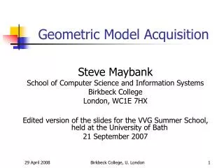
Geometric Model Acquisition Steve Maybank School of Computer Science and Information Systems Birkbeck College London, WC1E 7HX Edited version of the slides for the VVG Summer School, held at the University of Bath 21 September 2007 Birkbeck College, U. London
Geometric Model Acquisition • Aim: make a 3D model of a scene from two or more images taken from different viewpoints. • Why is it possible: the image differences depend in part on the shapes of the objects in the scene. Birkbeck College, U. London
Two Images of the Same Scene http://vasc.ri.cmu.edu/idb/images/stereo/fruit SOURCE "University of Illinois, Bill Hoff“ DESCRIPTION "Fruit on table, digitized from 35mm." Birkbeck College, U. London
Two Images of a Point in R3 Image 1 c1 • optical centre q1 • object point • p q2 • optical centre Epipolar plane: <c1,c2,x> c2• Image 2 Birkbeck College, U. London
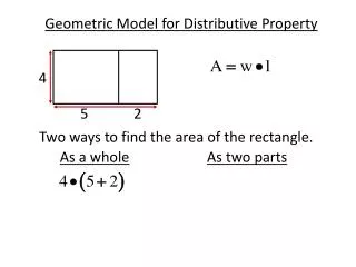
Corresponding Points • Points in different images correspond, if they are projections of the same scene point p. In projective coordinates, projection is a matrix application, Birkbeck College, U. London
Method for Finding Corresponding Points Birkbeck College, U. London
Example 1 of Correlation Based Matching Points in lh image =(150,100), (250,150), (350,250), (450,350), (250,450) Correlations (ρ) = 0.750, 0.685, 0.912, 0.644, 0.691 Search area = (2d+1)x(2d+1) box, d=20. Birkbeck College, U. London
What Do We Need for GAM? • Description of image formation in the camera. • Description of the relative positions of the cameras. • Equations involving the measurements, the scene points and the relative positions of the cameras. • Statistical description of the errors in the measurements. Birkbeck College, U. London
Pinhole Camera Small hole (optical centre) Viewing screen (image) Object Light rays Light tight box Central perspective projection model for image formation (Brunelleschi, 15th C.). Birkbeck College, U. London
Camera Coordinate Frame y Y x X Z • • (0,0,-f) (0,0,0) • (X,Y,Z) Origin (0,0,0) at the pin hole. Focal length of the camera = f. Axes of image coordinate frame are parallel to X, Y axes of the CCF. Image point = (-Xf/Z, -Yf/Z) Birkbeck College, U. London
Mathematical Version of the Camera Coordinate Frame Y Image plane y X x (0,0,f) • Z • (0,0,0) • • (X,Y,Z) Origin (0,0,0) at the pin hole. Focal length of the camera = f. The image is in front of the pin hole! Image point = (Xf/Z, Yf/Z). The minus signs have gone. Birkbeck College, U. London
Relative Position of the Cameras R, t The relative position of the cameras is described by an orthogonal matrix R and a translation vector t. Birkbeck College, U. London
Transformation of Coordinates ● p R, t If a point p has coordinates (X,Y,Z)T in the first CCF, then in the second CCF the same point p has coordinates Birkbeck College, U. London
Properties of Orthogonal Matrices Birkbeck College, U. London
Projection Ray Y ● X Z CCF Any scene point projecting to (x, y, f)T is on the projection ray. Birkbeck College, U. London
Projection Rays of Corresponding Points 1 ● The projection rays of corresponding points intersect at a scene point. Geometric model acquisition is based on this single constraint. For an extreme example, see http://www.wisdom.weizmann.ac.il/~vision/VideoAnalysis/Demos/Traj2Traj/hall.htm Birkbeck College, U. London
Projection Rays of Corresponding Points 2 ● The equations of the projection rays are known, but they hold in different coordinate systems. Birkbeck College, U. London
Transformation of Coordinates Birkbeck College, U. London
The Essential Matrix Birkbeck College, U. London
Model Acquisition Birkbeck College, U. London
Naïve Estimates of E Birkbeck College, U. London
Better Way of Estimating E Birkbeck College, U. London
Geometric Picture ● ● First image Second image Birkbeck College, U. London
Camera Calibration Measured pixel coordinates Ideal pixel coordinates Ideal CCF Camera calibration is a transformation from measured pixel coordinates to ideal pixel coordinates. Birkbeck College, U. London
Calibration Matrix Birkbeck College, U. London
Fundamental Matrix The fundamental matrix F is defined by Birkbeck College, U. London
Properties of E and F • det(E)=det(Tt)det(R)=0 • The matrix E is essential iff SingularValues(E) = (σ,σ,0) • det(F)=det(K~)det(E)det(K)=0 • The matrix F is fundamental iff det(F)=0. Birkbeck College, U. London
Minimal Data Birkbeck College, U. London
Books • D.A. Forsyth and J. Ponce. Computer Vision: a modern approach. Prentice Hall, 2003. • R.C. Gonzalez and R.E. Woods. Digital Image Processing. Second edition, Prentice Hall, 2002. Birkbeck College, U. London