Download
1 / 52
600 likes | 1.4k Views
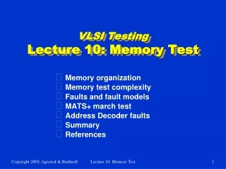
14. Memory testing. Motivation for testing memories (4) Modeling memory chips (6) Reduced functional fault models (17) Traditional tests (7) March tests (7) Pseudorandom memory tests (10). 1.1 Importance of memories. Memories dominate chip area (94% of chip area in 2014)

E N D
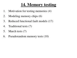
14. Memory testing • Motivation for testing memories (4) • Modeling memory chips (6) • Reduced functional fault models (17) • Traditional tests (7) • March tests (7) • Pseudorandom memory tests (10)
1.1 Importance of memories • Memories dominate chip area (94% of chip area in 2014) • Memories are most defect sensitive parts • Because they are fabricated with minimal feature widths • Memories have a large impact on total chip DPM level • Therefore high quality tests required • (Self) Repair becoming standard for larger memories (> 1 Mbit) % of chip area year
1.2 Memory chip cost over time Price of high-volume parts is constant in time; except for inflation Note: Slope of line matches inflation! Dollars per DRAM chip
1.3 Table with test times • Note: A memory is tested with several algorithms, which together may go through the total address space over 100 times • Effective test time for 16 Mb DRAM, using O(n) tests, is about 168 s • Test time reduced using on-chip parallelism (DFT and BIST)
1.4 Problems with testing memories • Number of bits/chip increases exponentially (4*in <3 years) • Price/bit decreases exponentially • Test cost has to decrease exponentially as well • Older traditional tests were of O(n2) • Current tests have to be of O(n) or less • DFT and BIST used to reduce test time to about O(n) • Area/cell decreases exponentially • Line widths decrease (more: opens, resistance) • Line distances decrease (more: shorts, couplings) • Cell leakage increases with reduced threshold voltages • Consequence • More complex fault behavior • More global fault behavior (ground bounce, coupling effects) Result:Number of bits to be tested increases exponentially, fault behavior becomes more complex, while test cost has to be same
2.1 Functional SRAM memory model Fig. 4.2 pag. 35
VDD VDD CMOS SRAM Cell Q4 Q3 L1 L2 WL WL Q6 Q6 Q5 Q5 Q2 Q1 Q2 Q1 VSS VSS BL BL BL BL 2.2 Electrical SRAM cell model • Structure of a CMOS SRAM cell (left cellbelow) • Q1--Q3 and Q2--Q4 form inverters (Q3 and Q4 are the load devices) • Inverters are cross coupled to form a latch • Q5 and Q6 are pass transistors • Addressing of a cell uses • a row address (using the word line WL) • a column address (using the bit lines BL and BL*) • Operations • Write: precharge BLs; drive BL, BL* and WL • Read: precharge BLs; drive WL; feed BLs to sense amplifiers SRAM Cell with Polysilicon Load Devices L1 and L2
WL Vcc BL Cell capacitor 2.3 Electrical DRAM cell model DRAM cell stores information as a charge in a capacitor • Cell capacitance 40 fF = 40* 10-15 F;BL capacitance 300 fF! (SRAM cell stores information in terms of the state of a latch) • This charge leaks away over time • DRAMs require refresh circuitry (Refresh rate: 64 ms) • DRAM cells require 1/4th the area of SRAM cells • DRAM cells dissipate less power (thicker gate oxide) • DRAMs are less sensitive to Soft Errors • DRAMs are slower • Operations • Read: precharge BL; drive WL; feed BL to sense amplifier • Write: drive BL; drive WL
2.4 Decoders • Decoders address a specific cell in the Memory Cell Array ‘MCA’ • If the MCA would be a vector, then 1 Mbit MCA requires 1M WLs • By arranging the cells in the MCA in a two-dimensional structure, a 1 Mbit MCA requires 1K WLs and 1 K BLs • This is a significant reduction in the decoder area! • Hence, the MCA is two dimensional and consists of rows and columns • The Column decoder selects a particular Column • The Row decoder selects a particular Row • Decoders may be simple logic gate structures Example of a simple k-input decoder
2.5 Read/write drivers The write driver can be rather simple • The data-to-be-written is presented on BL • The inverse data-to-be-written is presented on BL* The sense amplifier can be • a simple inverter; e.g. for small arrays, which have strong signals • a differential amplifier; for larger arrays, which have weak signals
Address Address decoder Memory cell array Read/write logic Data 2.6 The reduced functional model • For test purposes Functional model reduced (simplified) to three blocks • The functional faults also reduced: • single-cell faults (SAFs, TFs, etc.) • two-cell faults (Coupling faults) • k-cell faults (NPSFs) • The functional fault models have a hierarchy: 1. Stuck-at fault (SAF) 2. Transition fault (TF) 3a. Coupling fault (CF) 3b. Neighborhood pattern sensitive fault (NPSF)
3.1 Notation for describing faults • <…> describes a fault • <S/F> describes a single-cell fault • S describes the state/operation sensitizing the fault • A fault is sensitized when the fault effect is made present • F describes the faulteffect in the victim cell (v-cell) • <S;F> describes a two-cell fault (a Coupling Fault) • S describes the state/operation of the aggressor cell (a-cell) sensitizing the fault • F describes the fault effect in the v-cell • Examples • </0>: a SA0 fault </1>: a SA1 fault • </0>: an TF </1>: a TF • <;0>: a CFid <;1>: a CFid • <;0>: a CFid <;1>: a CFid 1-cell fault <S/F> / 2-cell fault <S;F> ;
w0 w0 w1 w1 Good cell S0 S1 S0 w0 w0 w1 w1 S1 SA1 fault SA0 fault 3.2 Stuck-At Fault (SAF) • The logic value of a Stuck-At cell or line is always: 0: a SA0 fault 1: a SA1 fault • Only one fault (a SA0 or a SA1) can be present at a time SAF fault type has two subtypes
VDD L1 L2 WL SOpF Q6 Q5 Q2 Q1 VSS BL BL 3.3 Stuck-Open Fault (SOpF) SOpF: A cell cannot be accessed; e.g., due to an open in its WL When a read operation is applied to a cell, the differential sense amplifier has to sense a voltage difference between BL and BL* • In case of an SOpF BL and BL* have the same (high) level Output Sense Amplifier: • fixedvalue (SOpF behaves as a SAF) • previous value of sense amplifier Detected when in a march element a ‘0’ and ‘1’ is read. Required form of the march element: (…,rx,…,rx*) 3. random (fault detectedprobabilistically) Every read operation detects the SOpF with a probability of 50%
S Q Cell R Q* w1 w0 w1 Cell with </0> TF S1 S0 w0 3.4 Transition fault (TF) • A cell fails to undergo the following transition(s): • Fails up-transition: a </0> TF • Fails down-transition: a </1> TF • Fault type has two subtypes: the </0> and the </1> TF • A single cell may contain both faults • The Set input may not work (e.g., SA0) • TheReset input may not work Test: Every cell should make and transition and be read Conceptual TF representation Defect
VDD L1 L2 WL Q6 Q5 DRF Q2 Q1 VSS BL BL 3.5 Data retention fault (DRF) DRF: A cell cannot retain its logic value • Typically caused by a broken pull-up device which causes the leakage current of the node with a logic 1 not to be replenished • After a time delay ‘Del’ (Typically: 100 ms Del 500 ms) the cell will flip • The DRF fault type has two subtypes, which may be present simultaneously in the same cell: <1T/0> and <0T/1> • <1T/0> means that a logic 1 will become a logic 0 after a delay time T
<;0> a-cell v-cell v-cell a-cell <;0> A B 3.6 Faults involving 2 cells: Coupling Faults ‘CFs’ CF: The state of, or an operation applied to, the a-cell (aggressor cell) forces or changes the state of the v-cell (victim cell) • Fault type Idempotent CF: CFid • A transition write operation (=0 1 & =10 change) applied to the a-cell forces the contents of the v-cell • CFid has4subtypes: <;0>, <;1>, <;0> and <;1> • The or write operations to a-cell sensitize the fault • The ‘0’ or ‘1’ are the fault effect in the v-cell • In addition, each subtype has twopositions: A. address of a-cell < address of v-cell B. address of a-cell > address of v-cell
3.7 Coupling faults (CFst, CFin) • State CF (CFst): A CF whereby the state of the a-cell forces a fixed value in the v-cell • Four fault subtypes : <1;0>, <1;1>, <0;0> and <0;1> • Each subtype has 2 positions: • addr. a-cell < addr. v-cell • addr. a-cell > addr. v-cell • Inversion CF (CFin):A transition write operation to the a-cell toggles the contents of the v-cell (Note: denotes toggling) • Two fault subtypes exist: <;> and <;> • Each subtype has 2 positions: • addr. a-cell > addr. v-cell • addr. a-cell < addr. v-cell Note: CFin not a realistic fault An SRAM cell is a latch, rather then a flip-flop Cannot toggle!
e a e e v a e v e e 3.8 Pattern sensitive fault (k-CF, PSF) • A k-Coupling Fault (k-CF), also called a Pattern Sensitive Fault (PSF), involves k cells which form a neighbourhood • The v-cell is also called the base cell • The k-1 non-v-cells are the deleted neighbourhood cells • The k cells can be anywhere in memory Example: Active PSF A CFid with k-2 enabling values a = a-cell, v = v-cell, e = enabling cell • Neighbourhood PSFs (NPSFs) more realistic • The cells have to be physical neighbours • Example: Active NPSF (ANPSF) a-cell sensitises fault in v-cell iff e-cells have enabling state PSF NPSF
CFid e e v e a a a e e e e v v v e e e e e e 3.9 Pattern sensitive fault (NPSFs) A Neighbourhood PSF (NPSF) is a restricted k-CF • The deleted neighbourhood cells have to be physically adjacent tothe base cell • Active NPSF (ANPSF): A conditional CFid • A CFid requiring the k-2 e-cells to have to have an enabling state • Passive NPSF (PNPSF): A conditional TF • A TF requiring the k-1 e-cells have to have an enabling state • Static NPSF (SNPSF): A conditional CFst • A CFst whereby the k-2 e-cells have to have an enabling state TF CFst
Probability R-defect 3.10 Validation of the fault models Performed by (Dekker, ITC’88) for SRAMs • 8 K*8 = 64 Kbits, 4 Transistor (4T) cells • technology: 4 m (Note: R-defect is defect resistivity) • Distribution for R-defect values assumed to be uniform • i.e., no FAB statistics taken into account Table shows likelihood of functional faults, as a function of the spot defect size Results: Two new fault models established: SOpF and DRF SAFs 50% CFs due to large spot defects CFin not present!
3.11 March tests: Concept and notation • A march test consists of a sequence of march elements • A march element consists of a sequence of operations applied to every cell, in either one of two address orders: 1. Increasing () address order; from cell 0 to cell n-1 2. Decreasing () address order; from cell n-1 to cell 0 Note: The address order may be any sequence of addresses (e.g., 5,2,0,1,3,4,6,7), provided that the address order is the exact reverse sequence (i.e, 7,6,4,3,1,0,2,5) • Example: MATS+ {(w0);(r0,w1);(r1,w0)} • Test consists of 3 march elements: M0, M1 and M2 • The address order of M0 is irrelevant (Denoted by symbol ) M0: (w0) means ‘for i = 0 to n-1 do A[i]:=0’ M1: (r0,w1) means ‘for i = 0 to n-1 do {read A[i]; A[i]:=1}’ M2: (r1,w0) means ‘for i = n-1 to 0 do {read A[i]; A[i]:=0}’
Case d: Case b: Case c: Case a: a1 v1 a2 v2 a2 v1 v a1 a1 v2 a2 a1 v1 v2 a2 Case e: Case f: v2 a a v1 v 3.12 Combinations of memory cell faults A memory may contain: • A single fault • Multiple faults (6 cases of CFs shown; ai is a-cell, vj is v-cell)) can be: • Unlinked: Faults do not interact (Cases a, b, c, e) • Linked: Faults do interact (Cases d, f) Linked faults have a common victim
3.13 Linked coupling faults • Case a: Two unlinked CFids; detected by the march test {(w0); (r0,w1);(w0,w1);(r1)} M0 M1 M2 M3 <;1> CFid sensitized by w1 operation of M1 detected by r0 of M1 <;0> CFid sensitized by w1 of M2, detected by r1 of M3 • Case b: Linked CFids • Cannot be detected by test of Case a (for unlinked CFids) because of masking • Linked faults require special, more complex, tests March elements Case b: <;1> Case a: <;1> <;0> <;0> a1 v1 v2 a2 a1 a2 v1=v2
Ax Cx Ax Cx Fault A Cy Ay Fault B Cx Ax Ax Cx Cy Cy Ay Ay Fault C Fault D 3.14 Address decoder faults (AFs) Functional faults in the address decoders: A. With a certain address, no cell will be accessed B. A certain address accesses multiple cells C. A certain cell is accesses with multiple addresses D. Certain cells are accessed with their own and other addresses Difficult fault: Read operations may produce a random result Reading from address Ay Cx=1 Cx=0 Ax Ax Cy=1 Cy=1 Ay Ay
Address Address decoder w2 Memory cell array x2 b2 z2 y2 Read/write logic x1 b1 z1 Data 3.15 Mapping read/write logic faults The reduced functional model consists of three blocks • the address decoder • the memory cell array (MCA) • the read/write logic Read/write logic faults can be mapped onto MCA faults • SAFs, TFs and CFs will de detected by tests for the MCA
Cx Ax Ax Cx Ax Cx Ax Cx Fault A Cy Cy Cy Ay Ay Ay Fault B Fault C Fault D 3.16 Mapping address decoder faults March tests for MCAFs detect AFs if they satisfy Cond. AF Cond. AF: The march test has to contain the following march elements 1. (rx,…,wx*) This means either (r0,…,w1) or (r1,…,w0) 2. (rx*,…,wx) Note: ‘…’ means any # of r or w operations Proof • Easy for Faults A, B and C • For Fault D the result of a read operation can be: • A deterministic function (Logical AND or OR) of read values • A random result (when the read cells contain different values)
Cx Ax Ax Av Ax Az Az Ax Ay Aw Av Ay Aw Cx Cy Cv Cz Cw Cx Cv Cx Cw Cz Cy Cy Ay 3.17 Mapping address decoder faults (cont.) Fault D: read result random if cells contain different values • Cond. AF-1: (rx,…,wx*) detects Faults D1 & D2 • When Ax written with x*, cells Cy...Cz are also written with x* • Fault detected when Cy is read: reads x* while expecting x • Cond. AF-2: (rx*,…,wx) detects Faults D1 & D3 • When Ax written with x, cells Cv...Cw are also written with x • Fault detected when Cw is read: reads x while expecting x* . Fault D2 Original Fault D Fault D3 Fault D1
4.1 Functional RAM chip testing • Purpose 1. Cover traditional tests (5) • Zero-One (MSCAN) • Checkerboard • GALPAT and Walking 1/0 2. Cover tests for stuck-at, transition and coupling faults (6) • MATS and MATS+ • March C- • March A and March B 3. Comparison of march tests (1)
4.2 Fault coverage of tests • When a test detects faults of a particular fault type, it detects: • all subtypes of that type; e.g., if it detects TFs is has to detect all </0> and </1> TFs • all positions of each subtype (addr. a-cell < or > v-cell) • A complete test detects all faults it is designed for It may, additionally, and unintentionally, detect also other faults But not all subtypes and not all positions of each of these faults Example: MATS+ : {(w0);(r0,w1);(r1,w0)} • Detects all AFs • Detects all SAFs • Detects all </0> TFs • Does not detect all </1> TFs MATS+ does not detect TFs Fault coverage of MATS+ </0> TFs AFs, SAFs
4.3 Traditional tests • Traditional tests are older tests • Usually developed without explicitly using fault models • Usually they also have a relatively long test time • Some have special properties in terms of: • detecting dynamic faults • locating (rather than only detecting) faults • Many traditional tests exist: 1.Zero-One (Usually referred to as Scan Test or MSCAN) 2.Checkerboard 3.GALPAT and Walking 1/0 4. Sliding Diagonal 5. Butterfly 6. Many, many others
4.4 Zero-One test (Scan test, (M)SCAN) • Minimal test, consisting of writing & reading 0s and 1s • Step 1: write 0 in all cells • Step 2: read all cells • Step 3: write 1 in all cells • Step 4: read all cells • March notation for Scan test: {(w0);(r0);(w1);(r1)} • Test length: 4*n operations; which is O(n) • Fault detection capability: AFs not detected • Condition AF not satisfied: 1. (rx,…,wx*) 2. (rx*,…,wx) • If address decoder maps all addresses to a single cell, then it can only be guaranteed that one cell is fault free • Special property: Stresses read/write & precharge circuits when Fast X addressing is used and sequence of write/read 0101.... data in a column! Fast X addressing Row 000000 stripe 111111 000000 111111 Checker 010101 board 101010 010101 101010 Columns Rows
4.5 Checkerboard • Is SCAN test, using checkerboard data background pattern • Step 1: w1 in all cells-W w0 in all cells-B • Step 2: read all cells • Step 3: w0 in all cells-W w1 in all cells-B • Step 4: read all cells • Test length: 4*2N operations; which is O(n) • Fault detection capability: • ConditionAF not satisfied : 1. (rx,…,wx*); 2. (rx*,…,wx) If address decoder maps all cells-W to one cell, and all cells-B to another cell, then only 2 cells guaranteed fault free • Special property: Maximizes leakage between physically adjacent cells. Used for DRAM retention test!! Step1 pattern Checkerboard data background
0 0 0 0 0 1 0 0 0 0 0 0 0 0 0 0 0 0 0 0 0 1 0 0 0 0 0 0 0 0 0 0 Walking 1/0 GALPAT 4.6 GALPAT and Walking 1/0 • GALPAT and Walking 1/0 are similar algorithms • They walk a base-cell through the memory • After each step of the base-cell, the contents of all other cells is verified, followed by verification of the base-cell • Difference between GALPAT and Walking 1/0 is when, and how often, the base-cell is read Base cell Base cell
GALROW 0 1 0 0 4.7 GALPAT and Walking 1/0: Properties • Tests can locate faults • GALPAT detects write recovery faults (Cause: slow addr. decoders) • Test length: O(n2):Not acceptable for practical purposes • Most coupling faults in a memory are due to sharing • a WL and the column decoder: cells in the same row • BLs and row decoder: cells in the same column • Subsets of GALPAT and Walking I/O used (BC= Base-Cell) • GALROW and WalkROW: Read Action on cells in row of BC • GALCOL and WalkCOL: Read Action on cells in column of BC Test length (assuming n1/2 rows and n1/2 columns): O(n3/2) Note: Test time for 4Mb 150 ns memory • For O(n2) test = O(20 days), and for O(n3/2) test = O(14 sec.)
5.1 March tests The simplest, and most efficient tests for detecting AFs, SAFs, TFs and CFs are march tests The following march tests are covered: • MATS+ • Detects AFs and SAFs • March C- • Detects AFs, SAFs, TFs, and unlinked CFins, CFsts, CFids • March A • Detects AFs, SAFs, TFs, CFins, CFsts, CFids, linked CFids (but not linked with TFs) • March B • Detects AFs, SAFs, TFs, CFins, CFsts, CFids, linked CFids
5.2 MATS+ • MATS+ algorithm: {(w0);(r0,w1);(r1,w0)} • Fault coverage • AFs detected because MATS+ satisfies Cond. AF (When reads, accessing multiple cells, return a random value) Cond. AF: 1. (rx,…,wx*) and 2. (rx*,…,wx) (1) satisfied by: (r0,w1) and (2) by: (r1,w0) • SAFs are detected: from each cell the value 0 and 1 is read • Test length: 5*n Note: If fault model is symmetric with respect to 0/1, /, and with respect to address a-cell < v-cell and address a-cell > v-cell, then each march tests has 3 equivalent tests 0s 1s: {(w0);(r0,w1);(r1,w0)} {(w1);(r1,w0);(r0,w1)} s s: {(w0);(r0,w1);(r1,w0)} {(w0);(r0,w1);(r1,w0)} 0s1s,ss: {(w1);(r1,w0);(r0,w1)}{(w1);(r1,w0);(r0,w1)}
5.3 March C- • March C (Marinescu,1982): an 11*n algorithm {(w0);(r0,w1);(r1,w0);(r0);(r0,w1);(r1,w0);(r0)} It can be shown that middle ‘(r0)’ march element is redundant • March C- (van de Goor,1991): a 10*n algorithm {(w0);(r0,w1);(r1,w0);(r0,w1);(r1,w0);(r0)} M0 M1 M2 M3 M4 M5 • Fault coverage of March C- • AFs: Cond. AF satisfied by M1 and M4, or by M2 and M3 • SAFs: Detected by M1 (SA1 faults) and M2 (SA0 faults) • TFs: </0> TFs sensitized by M1, detected by M2 (and M3+M4) </1> TFs sensitized by M2, detected by M3 (and M4+M5) • CFins detected • CFsts detected • CFids detected (see proof)
<;1> <;0> Case 1a a2a1v <;0> CFid a1 v 5.4 March C- detects CFids March C-: {(w0);(r0,w1);(r1,w0);(r0,w1);(r1,w0);(r0)} M0 M1 M2 M3 M4 M5 Proof for detecting CFs are all similar. Analyze all cases: • Relative positions of a-cell and v-cell 1. address of a-cell < v-cell; 2. address of a-cell > v-cell • Fault subtype a. CFid <;0>; b. CFid <;1>; c. CFid <;0>; d. CFid<;1> Consider Case1a: a-cell < v-cell and CFid <;0> • Fault sensitized by M3 and detected by M4 • If the CFid <;0>a1 (a-cell is a1) is linked to CFid <;1>a2, and address of a2 < a1 then linked fault will not be detected Reason: M3 will sensitize both faults, such that masking occurs Linked fault
5.5 March A & March B • March A algorithm (Suk,1981) {(w0);(r0,w1,w0,w1);(r1,w0,w1);(r1,w0,w1,w0);(r0,w1,w0)} M0 M1 M2 M3 M4 • March A (Test length: 15*n) detects • AFs, SAFs, TFs, CFins, CFsts, CFids • Linked CFids, but not linked with TFs • March A is complete: detects all intended faults • March A is irredundant: no operation can be removed • March B algorithm (Test length: 17*n) {(w0);(r0,w1,r1,w0,r0,w1);(r1,w0,w1);(r1,w0,w1,w0);(r0,w1,w0)} M0 M1 M2 M3 M4 • Detects all faults of March A • Detects CFids linked with TFs, because M1 detects all TFs
VDD L1 L2 WL SOpF Q6 Q5 Q2 Q1 VSS BL BL 5.6 Test requirements for detecting SOpFs An SOpF is caused by an open WL which makes the cell inaccessible • To detect SOpFs, assuming a non-transparent sense amplifier, a march test has to verify that a 0 and a 1 has to be read from every cell • This will be the case when the march test contains the March Element ‘ME’ of the form: (…, rx, …, rx*, …), for x = 0andx = 1. • This ME may be broken down into two MEs of the form: (…,rx,…) & (…, rx*,…), for for x = 0andx = 1. Example: The ME “(r0,w1,r1,w0,r0,w1)” satisfies the above requirement Note: Any test can be changed to detect SOpFs by making sure that the above requirement is satisfied by possibly adding a rx and/or a rx* operation to a ME Example: MATS+ {(w0);(r0,w1);(r1,w0)} becomes {(w0);(r0,w1,r1); (r1,w0,r0)}
VDD L1 L2 WL Q6 Q5 DRF Q2 Q1 VSS BL BL 5.7 Test requirements for detecting DRFs Any march test can be extended to detect DRFs • Every cell has to be brought into one state • A time period (Del) has to be waited for the fault to develop • Note: The time for Del is typically between 100 and 500 ms • The cell contents has to be verified (should not be changed) • Above three steps to be done for both states of the every cell Example: MATS+ {(w0);(r0,w1);(r1,w0)} becomes {(w0);Del;(r0,w1);Del;(r1,w0)}
6.1 Pseudo-Random ‘PR’ memory tests • Purpose • Explain concept of pseudo-random (PR) testing (1) • Compute test length of PR tests for SAFs and k-CFs (5) • Evaluation of PR tests (3) • PR pattern generators and test response evaluators (2) • Sources of material • Mazumder, P. and Patel, J.H. (1992). An Efficient Design of Embedded Memories and their Testability Analysis using Markov Chains. JETTA, Vol. 3, No. 3; pp. 235-250 • Krasniewski, A. and Krzysztof, G. (1993). Is There Any Future for Deterministic Self-Test of Embedded RAMs? In Proc. ETC’93; pp. 159-168 • van de Goor, A.J. (1998). Testing Semiconductor Memories, Theory and Practice. ComTex Publishing, Gouda, The Netherlands • van de Goor, A.J. and de Neef, J. (1999). Industrial Evaluation of DRAM Tests. In Proc. Design and Test in Europe (DATe’99), March 8-13, Munich; pp. 623-630 • van de Goor, A.J. and Lin, Mike (1997). The Implementation of Pseudo-Random Tests on Commercial Memory Testers. In Proc. IEEE Int. Test Conf., Washington DC, 1997, pp. 226-235
Reference data Reference data generator Control data generator Control data Response data RAM under test Compara tor Pass/Fail Reference RAM Reference data Compres sor Reference signature Control data generator Control data RAM under test Response data Compres sor Compara tor Response signature Pass/Fail 6.2 Concepts of PR memory testing • Deterministic tests • Control & Reference data for the RAM under test have predetermined values • The Response data of the RAM under test is compared with the expected data, in order to make Pass/Fail decision • Pseudo-random tests • Control data on some or all inputs established pseudo-randomly • Reference data can be obtained from a Reference RAM or, as shown, from as compressor
N RAM under test Address lines R/W line 1 B Data 6.3 Concepts of PR memory testing • Memory tests use • control values for: • Address lines (N) • R/W line (1) • write data values (B) • Deterministic test method Uses deterministic control and write data values • In a test the following can be Deterministic (D) or PR (R) • The Address (A): DA or RA • The Write (W) operation: DW or RW • The Data (D) to be written: DD or RD MATS+ is a DADWDD (Det. Addr, Det. Write, Det. Data) test • In a PR test at least ONE component has to be PR This can be: A (Addr.) &/or W (Write oper.) &/or D (Dat) PR tests are preferred above random tests: PR tests are repeatable
6.4 Pseudo-random tests for SAFs Some probabilities for computing the test length (TL) • The TL is a function of the escape probability ‘e’ • p: probability that a line has the value 1 • pa: probability that an address line has the value 1 • pd: probability that a data line has the value 1 • pw: probability that the write line has the value 1 • pA: probability of selecting address A (with z 0s and N-z 1s) pA = (1- pa)z * pa(N-z) • p1: probability of writing 1to address A; p1 = pd * pw * pA • p0: prob. of writing 0 to address A; p0 =(1- pd)* pw * pA • pr: probability of reading address A; pr = (1- pw)* pA
p1 1-p1 S1 SD0 S0 pr p0 6.5 Test length of PR test for SAFs Markov chain for detecting a SA0 fault (SA1 fault is similar) • S0:state in which a 0 is stored in the cell • S1: state in which a 1 should be in the cell • SD0: state in which SA0 fault is detected (absorbing state) • pS0(t) : probability of being in state S0 at time t • Initial conditions:pS0(0) =1-pI1, pS1(0) = pI1 , pSD0(0) =0 • pS0(t) = (1- p1)*pS0(t-1) + p0* pS1(t-1) • pS1(t) = p1*pS0(t-1) + (1- p0 -pr)* pS1(t-1) • pSD0(t) = pr*pS1(t-1) + pSD0(t-1) 1-(p0+pr) 1
6.6 Test length of PR test for SAFs • With deterministic testing fault detected with certainty • With PR testing fault detected with an escape probability ‘e’ • SA0 fault is detected when: pSD0(t) 1-e;T0(e) is TL for SA0 faults • T(e): The test length for SAFs is: T(e) = max(T0(e),T1(e)) Test length coefficient: Independent of n & proportional with ln(e) Test length coefficient
a e v e e 6.7 Test length of PR tests for k-CFs PR tests for k-CFids; the kcells may be located anywhere • For k =2 the test will be for CFids; for k >2 the for PSFs • To sensitize the CFid the k-2 cells require enabling valueG • For k = 5, there are k-2 = 3 enabling cells • Assume G = 110 = g1g2g3 thenpG = pd2*(1-pd) Several PR tests for k-CFs exist (2 shown below) • DADWRD (Det. Addr., Det. Write, PR Data) • Step 1: (w?); Initialize memory with PR values • Step 2: repeat t times: (r?,w?); Read and write new PR value • Step 3: (r?); Perform a final read • RARWRD (PR Addr, PR Write, PR Data) • Step 1: (w1); Initialize memory • Step 2: repeat t times {Generate PR Addr., perform read with pr=1-pw or a write with pw} CFid
6.8 Test length of PR tests for k-CFs Test length coefficients Fault coverage of RARWRD tests Note: k= Neigborhood Size • Observations • Number of operations roughly doubles if k increases by 1 • The DADARD test is more time efficient • The RARWRD test will detect more unanticipated faults • (Faults of unexpected or unknown fault models)