Sensor Network-Based Countersniper System
Sensor Network-Based Countersniper System. Gyula S, Gyorgy B, Gabor P, Miklos M, Branislav K, Janos S, Akos L, Andras N, Ken F Presenter Yamuna Krishnamurthy 2/7/05. Talk Outline. Problem/Solution PinPtr System Architecture Middleware Services Time Synchronization Message Routing

Sensor Network-Based Countersniper System
E N D
Presentation Transcript
Sensor Network-Based Countersniper System Gyula S, Gyorgy B, Gabor P, Miklos M, Branislav K, Janos S, Akos L, Andras N, Ken F Presenter Yamuna Krishnamurthy 2/7/05
Talk Outline • Problem/Solution • PinPtr • System Architecture • Middleware Services • Time Synchronization • Message Routing • Sensor Localization • Signal Detection • Sensor Fusion • Consistency Function • Search Algorithm • Performance Results • Future Work and Conclusion • Limitations/Discussion
Problem/Solution • Solution • Use an ad-hoc wireless sensor network-based system • Utilize many cheap sensors for • good coverage of direct signal • tolerance to failures • Detect via acoustic signals like muzzle blasts and shockwaves • Problem • Locate snipers in urban environments • Work with constraints of the urban environment • Multipath effects • Poor coverage due to shading effect of buildings • Overcome limitations of existing systems • Require direct line of sight • Rely on muzzle flash that can be suppressed • Centralized system not tolerant to sensor failure • Cost effectiveness
PinPtr - System Architecture • Ad-hoc wireless network of inexpensive sensors • Sensors can • detect muzzle blasts and acoustic shockwaves • Measure their time of arrival (TOA) • Message routing service delivers TOA to a base station • User Interface through base stations or PDAs • System field tested at the US Army McKenna MOUT (Military Operations in Urban Terrain) facility at Fort Nenning, GA
Custom Sensor Board and Mica2 Mote PinPtr – System Architecture
Custom Sensor Board and Mica2 Mote PinPtr Application Middleware • Time synchronization • Message routing • Data aggregation Operating System • Tiny OS (UC Berkeley) • Task scheduling • Radio communication • Clocks and timers • I/O • Power management Hardware • Mica Mote • Microcontroller • Multichannel receiver • 4KB RAM, 128KB Mem • Extension Interface • Acoustic Sensor Board • 3 acouastic channels • FPGA • Signal Processing • Measure TOA
MS - Time Synchronization • Flooding Time Synchronization Protocol (FTSP) • Synchronize local clock to clock of selected root node • Time stamping broadcasted radio message multiple times at sender and receiver nodes • Time stamps made when sending/receiving individual bytes • Reduce uncertainties of encoding/decoding and interrupt handling times • Final error corrected value embedded into message before end of transmission • Estimate global time by synchronizing with nodes a level above • Less communication overhead
MS - Time Synchronization • Alternate algorithm • Power conservation • Does not require continuous radio broadcast to synch time • Use data packets for time synch • Each node adds an age = (prev age) + (time pkt resent – time pkt received) • Time of event = T(recv) - age
MS - Message Routing • Gradient-Based best effort converge-cast protocol • Assign a root node • Route data from all nodes to the root node • Each node rebroadcasts data packets upto 3 times • Data packets reach the root through multiple paths • Fast and robust • Does not guarantee message delivery • Has significant message overhead
MS - Sensor Localization • Self-Localization procedure using ranging procedure • Ranging procedure • Broadcast a radio message followed by multiple chirps • Destination node samples each chirp by streaming microphone • Adds the samples together to increase signal to noise ratio • After recording, a digital band pass filter and peak detector estimate start of the first chirp • Range is computed using time of flight of the chirp • Assign unique time slots to adjacent nodes within two hops radius • In each time slot acoustic ranging procedure is initiated between the node and its neighbors • Measurements are propagated to the base • Base estimates the relative position of node to known anchor points through optimization procedures • Advantage • Reconfigure dynamically when sensors fail and new sensors are added • Disadvantages • Requirement of all nodes having 4 neighbors within 10mts range is not practical • Sounder makes sensors larger and consumes more power • Audible frequency of sounder makes detection by adversary easy • Ultrasonic sounders have lesser range
MS - Sensor Localization – Cont. • Passive acoustic sensor localization • Use external acoustic sources • In sniper scenario estimate sensor location through shots rather than sniper location with sensors • Produce 6 shots at known locations at unknown times and locate 4 sensors using linearization • Requires sensor to be in direct line of sight • Sensitive to small individual measurement errors • Non- analytic approach too slow • Produce shots at known locations and known times • Same as the active acoustic method • PinPtr Methodology • Due to shortcomings of above mentioned localization procedures PinPtr currently uses sensors at known locations.
Signal Detection • Incoming acoustic signal samples at 1MHz • Compressed using Zero Crossing (ZC) coding • Interval between ZCs is coded by storing • Start time of the interval (T) • Length of the interval (L) • Minimum or maximum signal value (Mm) • Previous signal avg amplitude (P) • Rise time (Γ) • Detect muzzle blast patters in the coded stream • Modeled with state machine states IDLE, POSSIBLE_START, DETECTED • When DETECTED start time at POSSIBLE_START is returned as TOA • Mote transmits TOA to base stations
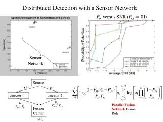
Sensor Fusion • Converge on the actual shooter position from positions calculated with TOA • Consistency Function using 3D space and time • Known values • Location (xi,yi,zi) of sensor making i th measurement • ti the time of arrival of detected muzzle blast • CΓ(x,y,z,t)= count (|ti(x,y,z,t)-ti| <= Γ) i=1,K,N • Search algorithm for convergence • Generalized bisection based on interval arithmetic • Create 4-dimensional spaces with the intervals [xmin,xmax]x [ymin,ymax]x [zmin,zmax]x [tmin,tmax] • Determine CΓfor each of the spaces • Select the area with CΓmax • Bisect the area along the longest dimension and repeat from 1-4 till maximum region is less than vΓ/2 for space and Γ/2 for time • Shooter position falls in this max area
Performance Results • Experimental setup • 56 motes • 20 different known shooter positions were used • 171 shots were fired
Performance Results • Shooter localization error • Elevation info eliminated for 2D • 3D errors are more as sensors were mostly positioned on the ground • Error Sources • Time Synchronization errors • Sensor localization errors
Performance Results • Sensor Density • Effects signal detection • Increases shooter localization error
Performance Results • Sensor Fusion • Compare analytic solution to the fusion algorithm • Analytic solution compares to fusion algorithm when no error readings are included • With error readings fusion algorithm provides a much better solution
Future Work and Conclusion • Future Work • Provide power management • Use shockwave signal • Support multiple shots with sensor fusion algorithm • Use post-facto time synchronization to conserve power • Use system in other Concepts of Operations • Reconnaissance missions • Protect convoy routes • Work on sensor self-localization techniques • Conclusion • PinPtr provides a counter-sniper system • Provides efficient algorithms for time synchronization and shooter/sensor localization • Good experiment to reassure actual deployment
Limitations/Discussion • Since PinPtr does not employ shockwave signals and relies on muzzle blast it may not work when silencers are used • Deployment of sensors in actual urban environment like NY is not trivial • Does not provide for power conservation hence battery life can be an issue since these systems typically need to be available always • Cannot deal with multiple shots fired by multiple snipers • No self-localization performed hence cannot dynamically configure with change in number of sensors