Download
1 / 89
890 likes | 1.09k Views
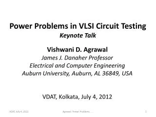
Invited Seminar Power and Time Tradeoff in VLSI Testing. Vishwani D. Agrawal James J. Danaher Professor Dept. of Electrical and Computer Engineering Auburn University, Auburn, AL 36849 vagrawal@eng.auburn.edu http://www.eng.auburn.edu/~vagrawal Heritage Institute of Technology

E N D
Invited SeminarPower and Time Tradeoff in VLSI Testing Vishwani D. Agrawal James J. Danaher Professor Dept. of Electrical and Computer Engineering Auburn University, Auburn, AL 36849 vagrawal@eng.auburn.edu http://www.eng.auburn.edu/~vagrawal Heritage Institute of Technology Department of Computer Science Kolkata, India, July 13, 2012 Agrawal: Power and Time Tradeoff . . .
Outline • Power consumption in VLSI circuits. • Test time. • Power constrained test. • Test scheduling for SoC devices. Agrawal: Power and Time Tradeoff . . .
Power Agrawal: Power and Time Tradeoff . . .
CMOS Logic (Inverter) VDD PMOS transistor No current flows from power supply! Where is power consumed? NMOS transistor GND F. M. Wanlass and C. T. Sah, “Nanowatt Logic using Field-Effect Metal-Oxide-Semiconductor Triodes,” IEEE International Solid-State Circuits Conference Digest, vol. IV, February 1963, pp. 32-33. Agrawal: Power and Time Tradeoff . . .
CMOS Gate Power v(t) V R = Ron i(t) vi (t) v(t) i(t) Large resistance C isc(t) isc(t) and Leakage Ground Leakage current time Agrawal: Power and Time Tradeoff . . .
Components of Power • Dynamic • Signal transitions • Logic activity • Glitches • Short-circuit (small) • Static • Leakage Ptotal =Pdyn+Pstat =Ptran+Psc+Pstat Agrawal: Power and Time Tradeoff . . .
Power Considerations in Design • A circuit performs certain function. Its design must allow the power consumption necessary to execute that function. • Circuit may be implemented low power dissipation in the functional mode. • Power buses are laid out to carry the maximum current necessary for the function. • Heat dissipation of package conforms to the average power consumption during the intended function. • Layout design and verification must account for “hot spots” and “voltage droop” – delay, coupling noise, weak signals. Agrawal: Power and Time Tradeoff . . .
Testing Differs from Functional Operation Other chips VLSI chip System outputs System inputs system Functional outputs Functional inputs Agrawal: Power and Time Tradeoff . . .
Method of Testing Packaged or unpackaged device under test (DUT) DUT output for comparison with expected response stored in ATE VLSI chip Test vectors: Pre-generated and stored in ATE Power Clock Automatic Test Equipment (ATE): Control processor, vector memory, timing generators, power module, response comparator Agrawal: Power and Time Tradeoff . . .
Functional inputs: Functionally meaningful signals Generated by circuitry Restricted set of inputs May have been optimized to reduce logic activity and power Test vectors: Functionally irrelevant signals Generated by software to test modeled faults Can be random or pseudorandom May be optimized to reduce test time; can have high logic activity May use testability logic for test application Functional Inputs vs. Test Vectors Agrawal: Power and Time Tradeoff . . .
An Example VLSI chip in system operation 8-bit 1-hot vectors Binary to decimal converter VLSI chip 3-bit random vectors system VLSI chip under test VLSI chip High activity 8-bit test vectors from ATE Agrawal: Power and Time Tradeoff . . .
Comb. Circuit Power Optimization • Given a set of test vectors • Reorder vectors to minimize the number of transitions at primary inputs Combinational circuit (tested by exhaustive vectors) 01010101 00110011 00001111 11 transitions 01111000 Rearranged vector set 00110011 produces 7 transitions 00011110 Agrawal: Power and Time Tradeoff . . .
Reducing Comb. Test Power Original tests: V1 V2 V3 V4 V5 1 3 4 V1 V2 V3 1 1 0 0 0 1 0 1 0 0 1 0 1 0 1 1 0 1 1 1 3 1 2 3 2 1 V4 V5 10 input transitions 2 Reordered tests: V1 V3 V5 V4 V2 1 0 0 0 1 1 1 0 0 0 1 1 1 0 0 1 1 1 1 0 Traveling salesperson problem (TSP) finds the shortest distance closed path (or cycle) to visit all nodes exactly once. But, we need an open loop solution. 5 input transitions Agrawal: Power and Time Tradeoff . . .
Open-Loop TSP 1 • Add a node V0 at distance 0 from all other nodes. • Solve TSP for the new graph. • Delete V0 from the solution. 3 4 V1 V2 V3 0 0 3 0 2 1 V0 2 3 1 V4 V5 0 2 0 Agrawal: Power and Time Tradeoff . . .
Combinational Vector Ordering • TSP has exponential complexity; good heuristics are available. • For other extensions: • V. Dabholkar, S. Chakravarty, I Pomeranz and S. Reddy, “Techniques for Minimizing Power Dissipation in Scan and Combinational Circuits During Test Application,” IEEE Trans. CAD, vol. 17, no. 12, pp. 1325-1333, Dec. 1998. • Typical average power saving: • 30-50% • 50-60% with vector repetition (to satisfy peak power) Agrawal: Power and Time Tradeoff . . .
Traveling Salesperson Problem • A. V. Aho, J. E. Hopcroft anf J. D. Ullman, Data Structures and Algorithms, Reading, Massachusetts: Addison-Wesley, 1983. • E. Horowitz and S. Sahni, Fundamentals of Computer Algorithms, Computer Science Press, 1984. • B. R. Hunt, R. L. Lipsman, J. M. Rosenberg, K. R. Coombes, J. E. Osborn and G. J. Stuck, A Guide to MATLAB for Beginners and Experienced Users, Cambridge University Press, 2006. Agrawal: Power and Time Tradeoff . . .
Example: A Branch and Bound Method • A combinational circuit is tested by a set of five vectors. The test system initializes to the first vector 0000, which should be retained as the starting vector. Remaining vectors can be arbitrarily sequenced. Find the minimum energy test sequence. How much does your sequence save over the original sequence? The given test vector sequence is: Vector number 1 2 3 4 5 0 1 1 0 1 0 1 0 1 0 0 1 0 1 0 0 1 0 0 1 Agrawal: Power and Time Tradeoff . . .
Begin with a Greedy Solution Designated start 1 2 4 5 • 2 • 1 2 1 2 4 3 4 3 3 Agrawal: Power and Time Tradeoff . . .
Branch and Bound Search Slack = 6 1 Edge weight = 4 2 1 2 Slack = 2 2 3 5 4 3 2 1 3 2 3 All searches terminate before reaching leaf node. Minimum path length = 6 3 4 5 2 4 5 2 S = 0 S = 0 4 Slack = – 1 2 4 Terminate search when slack ≤ 0 2 4 Greedy path Length = 6 Agrawal: Power and Time Tradeoff . . .
C6288: Test Vector Ordering Paul Wray, “Minimize Test Power for Benchmark Circuit c6288 by Optimal Ordering of Vectors,” Class Project, ELEC 5270, Spring 2009. PowerPoint Presentation and Report: www.eng.auburn.edu/~vagrawal/COURSE/E6270_Spr09/course.html Agrawal: Power and Time Tradeoff . . .
Scan Testing Primary outputs Primary inputs Combinational logic Scan-out SO Scan flip- flops D’ D SO D 1 0 Scan enable SE DFF mux D’ SI Scan-in SI SE Agrawal: Power and Time Tradeoff . . .
Some Properties of Scan Testing • Two modes of operation: • Normal mode • Scan mode • Three-step test application: • Scan-in: sets inputs of logic in scan mode. • Capture: captures logic outputs in normal mode. • Scan-out: observes captured outputs in scan mode. • Tests are non-functional; some tests may consume excess power and could have been intentionally avoided in functional mode. Agrawal: Power and Time Tradeoff . . .
Example: State Machine Functional transitions Functional state transitions S1 S5 S2 S4 S3 State encoding S1 = 000 S2 = 001 S3 = 010 S4 = 011 S5 = 100 Agrawal: Power and Time Tradeoff . . .
Reduced Power Design Functional transitions Functional state transitions S1 S5 S2 S4 S3 Reduced power state encoding S1 = 000 S2 = 011 S3 = 001 S4 = 010 S5 = 100 Agrawal: Power and Time Tradeoff . . .
Scan Testing: Shift-in, Shift-out Scan transitions Primary inputs Primary outputs Combinational logic Scan-out 100 FF=0 FF=0 FF=1 Shift-out transition Scan-in 010 Shift-in transition Shift-in transitions = Σ (scan chain length – position of transition) Shift-out transitions = Σ (position of transition) Agrawal: Power and Time Tradeoff . . .
Scan Testing: Capture Primary inputs 1 0 Primary outputs 1 1 Combinational logic Capture transitions: 3 Note that 101 is not a functional state in the reduced power state encoding. 1 0 1 FF=0 FF=1 FF=0 Agrawal: Power and Time Tradeoff . . .
A Four Flip-Flop Example Combinational Logic 0 1 0 1 0 1 0 1 0 0 0 1 0 0 0 1 0 0 0 0 Scanout 10 transitions F4 F3 F2 F1 0 0 0 0 0 1 0 1 Agrawal: Power and Time Tradeoff . . .
Change Scan Chain Order Combinational Logic 0 0 0 0 0 1 1 0 0 0 0 0 0 0 0 1 0 0 0 0 F4 F3 F2 F1 2 transitions 0 Scanout 0 0 1 1 0 0 0 Agrawal: Power and Time Tradeoff . . .
Capture Power Combinational Logic 1 0 1 1 Input vector 0 1 0 1 Output vector 3 transitions F4 F3 F2 F1 1 Scanout 0 1 Next vector states 0 Agrawal: Power and Time Tradeoff . . .
Vector Order - Select Next Vector Combinational Logic 1 0 1 1 Input vector 0 1 0 1 Output vector 3 transitions F4 F3 F2 F1 1 Scanout 1 0 Captured response Next vector states 1111 or 1100 or 0011 Select 1100 1 Agrawal: Power and Time Tradeoff . . .
Dynamic Power of Scan Test • Capture power can be reduced: • A vector generation problem • Shift-in and shift-out power is reduced by vector ordering. • Further reduction by scan chain ordering: • Construct a flip-flop node graph; edges weighted with shift in/shift out activity • Find shortest distance Hamiltonian paths between all node pairs • Select the path that minimizes shift power Agrawal: Power and Time Tradeoff . . .
Shift-in and Shift-out Matrices N Scan flip-flops: F1through FN; M vectors: V1through VM F1 → F2· → · Fj· → ·Fk·→ · FN F1→F2 → · Fj · → ·Fk· → · FN V1 0 1 ··· 1 ··· 0 ··· 1 1 1 ··· 1 ··· 0 ··· 0 V2 1 1 ··· 0 ··· 0 ··· 0 0 1 ··· 1 ··· 1 ··· 0 ··· ··· ··· ··· ··· ··· ··· ··· ··· ··· ··· ··· ··· ··· ··· ··· ··· IjIkOj Ok ··· ··· ··· ··· ··· ··· ··· ··· ··· ··· ··· ··· ··· ··· ··· ··· ··· VM 0 0 ··· 1 ··· 1 ··· 0 1 0 ··· 0 ··· 0 ··· 1 Flip-flop states for test input Test output states Agrawal: Power and Time Tradeoff . . .
A Complete Graph wjk = Hamming(Ij, Ik) + Hamming(Oj, Ok) w12 F1 F2 w13 w23 w16 w24 w26 w14 w25 w15 F3 F6 w36 w46 w35 w56 w34 F5 F4 w45 Agrawal: Power and Time Tradeoff . . .
Graph Solutions for Scan Power • High complexity of Hamiltonian path finding requires use of heuristics. • Average power saving: ~30-50% logic, ~10-20% flip-flops. • Y. Bonhomne, P. Girard, Landrault, and S. C. Pravossoudovtich, “Power Driven Chaining of Flip Flops in Scan Architectures,” Proc. International Test Conf., 2002, pp. 796–803. • Y. Bonhomne, P. Girard, L. Guiller, Landrault, and S. C. Pravossoudovtich, “Power-Driven Routing-Constrained Scan Chain Design,” J. Electronic Testing: Theory and Applications, vol. 20, no. 6, pp. 647–660, Dec. 2004. Agrawal: Power and Time Tradeoff . . .
Low Power Scan Flip-Flopwith Gated Data SO SO D 1 0 D mux D’ mux D’ DFF DFF SI SI SE CK CK SE SFF: Scan FF cell SFF-GD: Gated data scan FF cell Agrawal: Power and Time Tradeoff . . .
Low Power Scan Flip-Flopwith Gated Clock and Data SO D 1 0 mux D’ DFF SI CK SE SFF-GCKD: Gated clock and data scan FF cell Agrawal: Power and Time Tradeoff . . .
s5378: Normal Mode Operation • 1,000 random vectors • Clock period = 50ns • Technology: TSMC025 Agrawal: Power and Time Tradeoff . . .
s5378: Scan Test • Mentor Graphics Fastscan, 98.9% coverage • Clock period = 50ns • Technology: TSMC025 Agrawal: Power and Time Tradeoff . . .
Reference for Power Analysis • J. D. Alexander, Simulation Based Power Estimation For Digital CMOS Technologies, Master’s Thesis, Auburn University, Dept. of ECE, December 2008. Agrawal: Power and Time Tradeoff . . .
Shift Register Takes Most Power D D Q D Q D Q D Q Output D Q D Q D Q D Q CK Agrawal: Power and Time Tradeoff . . .
Reduced-Power Shift Register D D Q D Q D Q D Q Output multiplexer D Q D Q D Q D Q CK(f/2) Flip-flops are operated at full voltage and half the clock frequency. Agrawal: Power and Time Tradeoff . . .
Power Consumption of Shift Register P = C’VDD2f/n 16-bit shift register, 2μ CMOS 1.0 0.5 0.25 0.0 Normalized power C. Piguet, “Circuit and Logic Level Design,” pages 103-133 in W. Nebel and J. Mermet (ed.), Low Power Design in Deep Submicron Electronics, Springer, 1997. 1 2 4 Degree of parallelism, n Agrawal: Power and Time Tradeoff . . .
Low Power Scan Flip-FlopReducing Shift Power Scanin D Q FFN D Q FF2 D Q FF1 Scanout Multi-phase clock generator Scan Enable CLK Agrawal: Power and Time Tradeoff . . .
Test Time Agrawal: Power and Time Tradeoff . . .
Scan Testing PI PO SFF SCANOUT Combinational logic SFF SFF SE or TCK Not shown: CK or MCK/SCK feed all SFFs. SCANIN Agrawal: Power and Time Tradeoff . . .
Test Time • Total scan test time (Number of scan test clock cycles × clock period): • TT = NT = [(ncomb+ 2) nsff + ncomb + 4] × T • Where, ncomb= number of combinational vectors • nsff= number scan flip-flops in the longest scan chain • T = scan clock period • Example: 10,000 scan flip-flops in longest chain, 1,000 comb. vectors, total scan test length, TT ≈ 107T. • Reference: • M. L. Bushnell and V. D. Agrawal, Essentials of Electronic Testing for Digital, Memory and Mixed- Signal VLSI Circuits, Springer, 2000. Agrawal: Power and Time Tradeoff . . .
Scan Power During a Clock Cycle Chip current, i(t) time 0 Clock period, T T Cycle energy, E = VDD ∫ i(t) dt 0 Cycle power, P = E/T Agrawal: Power and Time Tradeoff . . .
Scan Power During Test WithSynchronous Clock Emax Pmax Cycle Energy, E Cycle power, P E E E E E E P E P P E P P P P P 1 2 3 4 5 6 7 8 Clock cycles T T T T T T T T Scan clock period, T = Emax/Pmax Agrawal: Power and Time Tradeoff . . .
Test Time for Synchronous Clock N Emax TTsync = NT = ———— Pmax Where, N = Number of scan test clock cycles Agrawal: Power and Time Tradeoff . . .
Power vs. Time • A good test: • Should not exceed given power budget, Pmax • Have short test time, time → cost • Reduce power: • Use low activity vectors ⇒ slower rise in fault coverage ⇒ more vectors ⇒ longer test time • Reduce test time: • Use high efficiency vectors ⇒ produce high activity ⇒ increase test power Agrawal: Power and Time Tradeoff . . .