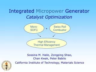
Integrated Micropower Generator
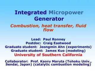
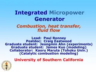
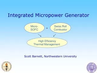
Integrated Micropower Generator. Micro- SOFC. Swiss Roll Combustor. +. Sossina Haile, David Goodwin, Caltech Steve Visco, Lutgard de Jonghe, Craig Jacobson, LBNL Scott Barnett, Northwestern University Paul Ronney, University of Southern California. High Efficiency Thermal Management.

Integrated Micropower Generator
E N D
Presentation Transcript
Integrated Micropower Generator Micro- SOFC Swiss Roll Combustor + Sossina Haile, David Goodwin, Caltech Steve Visco, Lutgard de Jonghe, Craig Jacobson, LBNL Scott Barnett, Northwestern University Paul Ronney, University of Southern California High Efficiency Thermal Management
Outline • Program Overview (Haile) • Power Generation Strategies • Integrated Micropower Generator (IMG) • Swiss Roll Heat Exchanger • Single Chamber Fuel Cell (SCFC) • Technical Program • SCFC Modeling (Goodwin) • SCFC Development (Haile, Barnett) • Fuel Cell Fabrication (Visco) • Afterburner Catalysts (Haile) • Swiss Roll Heat Exchanger: Simulation & Fabrication (Ronney) • Administrative Aspects (Haile) • Research Schedule and Milestones • Management & Reporting
Micropower Generation Strategies High power density vs. High energy density • Thermoelectrics (thermal to electric) • Manufacture by electrodeposition and MEMS methods • Heat source required, low efficiency (5%) • Microturbines (chemical to mechanical to electric) • Reasonable efficiency, fuel flexibility • High RPM tight tolerances, friction losses • Lithium batteries (“chemical” to electric) • Low maintenance, simple system • Insufficient energy density • Fuel Cells (chemical to electric) • Chemical fuels have high energy and power densities • Heat loss has limited micro-FCs to low temperatures • Lower efficiency, poor fuel flexibility
Concept Components • “Swiss roll” heat exchanger • Heat incoming gas with (cooling) outgoing gases • Reduced temperature SOFC (300-500ºC) • Minimize thermal stress • Retain high T advantages • Single chamber fuel cell • No seals required • Insensitive to cracks • Catalytic after-burner • Maintain temperature • Consume unreacted hydrocarbons • Micro-aspirator • Targets • Power density: 50-100mW/cm2, • Total volume: ~2 × 2 × 1.5cm3 • Total weight: ~10g
Swiss Roll Thermal Management Strategy: Transfer heat from exhaust to incoming gases • Linear counterflow heat exchanger • Linear device rolled up into 2-D “Swiss Roll” • 2-D device rolled up into toroidal “Swiss Roll” Temperatures significantly greater than 500C can be maintained
strip fuel oxidant Single Chamber Solid Oxide Fuel Cells • Hibino et al. Science (2000) • Fuel & oxidant mixed • Best reported performance • Power density: 644 mW/cm2 • Conditions: CH4 + Air; 550C • Strip or stacked geometry fuel + oxidant by-products CH4 + ½ O2 CO + 2H2 H2 + O= H2O + 2e- CO + O= CO2 + 2e- ½ O2 + 2e- O= conventional SOFC stacked CH4 + 4O= CO2 + 2H2O +8e- ½ O2 + 2e- O= seals
Multilayer geometry (1-cell) Ce0.8Sm0.2O1.9 (150mm) Ni-SDC (10:90 wt) Sm0.5Sr0.5CoO3 Variety of fuels, 18 vol% in air 1 – 10 cm/sec fluid velocities Ethane highest power 400 mW/cm2, 500°C State of the Art in SCFCs Hibino et al. Science (2000) 550°C ethane Limited by electrolyte resistance! 550°C 0.5mm 0.15mm Hibino et al. J. Electrochem. Soc. (2000)
SCFC Operational Parameters • Component materials: Electrolyte and Electrodes • Initial demonstrations, mixed O=/ H+ conducting electrolyte • Recent experiments, O= conductor • Reactions appear simpler with O= conductor • Need for ‘reduced temperature’ components/materials • Multi-cell Geometry • Multilayer stack allows greater design flexibility than strip • Extensive experience in multilayer stacks at LBNL • Experiments begin with anode or electolyte supported design • Fuels • Methane, ethane, propane, butane all demonstrated • Propane offers best microaspiration characteristics,handle as a liquid, relatively easy partial oxidation • Simulations begin with methane and propane
Early Design Decisions • Electrolyte, anode, cathode and fuel selection highly interdependent • Initial Proposal: parallel investigations • H+ and O= conducting electrolytes • Methane, ethane, propane and higher hydrocarbons • DARPA Feedback: early selection • O= conducting electrolye • Propane fuel • Program restructuring • Eliminate H+ based SCFC development (CIT) • Redistribute O= based SCFC development effort
Operational Targets • Fuel cell performance: 50 – 100 mW/cm2 • Total fuel cell area: 2.5cm2 • Device power output: 125 – 250 mW • 5 cell stack vol: (1 0.5 cm2 0.2 cm 5) • 1 cm/edge for 2-D Swiss roll • Device total: 2 2 1.5 cm3, ~ 10g • Propane, 2 cm3 tank, 40% efficiency 0.8Wh/cm3, 0.6 Wh/g
Challenges and Opportunities • Catalysts • Highly selective cathode and anode • Afterburner • Reaction pathways • Design & operation parameters • Fuel-to-air ratio, bypass air ratio • Flow rates, residence times • Fuel cell channel thickness, area • Swiss roll channel thickness, # turns • Computational effort • Avoid costly Edisonian “try and tinker” approach
Challenges and Opportunities • Fabrication: fuel cell and heat exchanger • Fuel cell materials compatibility • Multilayer fuel cell vs. single layer with strip electrodes • Anode vs. cathode supported design • Thermally insulating oxides for Swiss roll structure • Incorporation of fuel cell into Swiss roll heat exchanger • Supplementary air intake for complete combustion • Power extraction via appropriate wiring • Start-up via self-starting fuels/catalysts or battery powered resistive heating
Electrolyte selection Fuel selection SCFC simulation & model experiments Cathode materials Anode materials SCFC fabrication Swiss roll modeling & fabrication Catalytic afterburner Microaspirator Complete (doped ceria) Complete (propane) D. Goodwin & S. Haile (CIT) S. Haile (CIT) + NWU S. Barnett (NWU) + CIT S. Visco (LBNL) P. Ronney (USC) S. Haile (CIT) + USC P. Ronney (USC) Revised Responsibilities
Fuel Cell Simulations D. Goodwin, Caltech Swiss Roll Fab. System Simulations P. Ronney, USC Fuel Cell Fab. Integration w/Swiss Roll LBNL team Integrated Effort Design optimizationvia simulations Fuel celldevelopment Catalystdevelopment Cathode Dev. Catalyst Dev. S. Haile, Caltech Anode Dev. S. Barnett, NWU Fuel cellfabrication Systemintegration