Integrated Micropower Generator
250 likes | 577 Views
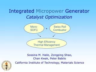
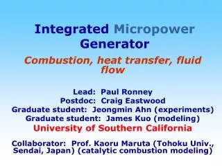
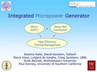
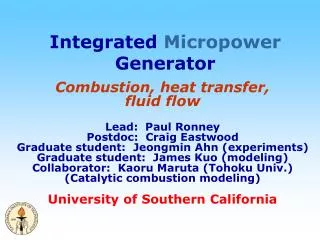
Integrated Micropower Generator. Combustion, heat transfer, fluid flow Lead: Paul Ronney Postdoc: Craig Eastwood Graduate student: Jeongmin Ahn (experiments) Graduate student: James Kuo (modeling) Collaborator: Kaoru Maruta (Tohoku Univ.) (Catalytic combustion modeling)

Integrated Micropower Generator
E N D
Presentation Transcript
Integrated Micropower Generator Combustion, heat transfer, fluid flow Lead: Paul Ronney Postdoc: Craig Eastwood Graduate student: Jeongmin Ahn (experiments) Graduate student: James Kuo (modeling) Collaborator: Kaoru Maruta (Tohoku Univ.) (Catalytic combustion modeling) University of Southern California
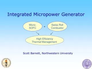
Integrated Micropower Generator Objectives • Thermal / chemical management for SCFC • Deliver proper temperature, composition, residence time to SCFC • Oxidize SCFC products Task progress • Catalytic “Swiss roll” combustor experiments • Numerical modeling • Fuel cell testing
Lessons learned from earlier work • Heat losses limit performance of Swiss roll (or any combustor) at low Re • Heat transfer along dividing wall of Swiss roll limits burner performance, especially at low Re • Catalytic combustion greatly aids low-Re performance • Emphasize low-Re catalytic combustion, minimize thermal losses, minimize wall thickness and conductivity
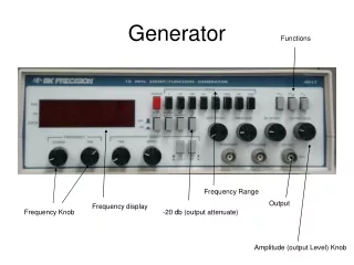
2D Inconel macroscale burner • 3 turn, 3.5 mm channel width, 5 cm tall • 7 thermocouples (1 center, 1 each inlet & outlet turn) • Mass flow controllers, LabView data acquisition & control
Quenching limits in Swiss roll • Dual limits - low-velocity (heat loss) and high-velocity (blow-off) • Out-of-center combustion regime (unstable operation) • Very low Re (< 4) possible with catalytic combustion • Lean limit can be richer than stoichiometric (!) (catalytic only) • Weinberg low-Re performance very poor (more heat losses?)
Quenching limits in Swiss roll • Lower Re - flame always centered - heat recirculation needed to obtain sufficiently high temperature to sustain reaction • Maximum temperatures near stoichiometric
Quenching limits in Swiss roll • Higher Re - flame not centered near stoichiometric - less heat recirculation needed to sustain combustion - reaction zone moves toward inlet • Center cool due to heat losses
Quenching limits - continued • Ratio of (estimated) heat loss to heat generation ≈ constant for low Re (indicating heat loss induced extinction) • Ratio decreases at higher Re (indicating “blow-off“ type extinction)
Quenching limits - continued • Temperatures dramatically lower with Pt catalyst - < 500 K possible even at Re < 4
Thermal behavior of Swiss roll • Peak temperatures correlate well with heat recirculation parameter = {Abs(Ti-Ti-1)/(Tad-T∞)}
Thermal performance • Titanium burner - lower wall conductivity, same wall thickness & number of turns - higher peak temperatures • Also lower coefficient of thermal expansion
inlet outlet Numerical model • FLUENT, 2D, 8216 grid points • Conduction (solid & gas), convection (gas), radiation (solid-solid only) • Temperature-dependent gas properties • 1-step chemistry (Westbrook & Dryer) • Boundary condition: • Inlet: 300K, 3 m/s (Re = 700), 1 mole % propane in air (stoichiometric = 4.02%) • Outlet: Pressure outlet • Heat loss: volumetric term to simulate heat loss in 3rd dimension • Radiation: discrete ordinates, unit emissivity on all surfaces
Model results - radiation & heat loss • Reaction near center (centered for weaker mixtures near extinction limit) • Peak T near peak reaction rate
Model results - radiation, no heat loss • Minor effect of heat loss for high Re (=700) case shown, much greater effect for lower Re
Model results - no radiation, heat loss • Extreme case - low Re (23), high fuel concentration (3.0%) • Thin reaction zone (laminar flame), anchored near inlet (doesn’t need heat recirculation to exist), rest of burner acts as heat sink
Model results - no radiation, heat loss • Higher temperatures (by ≈150K) without radiation), more nearly isothermal • Radiation transfers heat between walls but not directly to gas - similar effect as increasing wall thermal conductivity • Important for scale-down - radiation will be less significant at smaller scales due to higher gradients for conduction • Boltzman number T3d/
Numerical modeling - 3D • 3D modeling initiated with 4-step chemical model (Hauptmann et al.) • (1) C3H8(3/2)C2H4 + H2 • (2) C2H4 + O2 2CO + 2H2 • (3) CO + (1/2)O2 CO2 • (4) H2 + (1/2)O2 H2O • 3D simulation (217,000 cells) confirms most of heat loss is in axial (z) direction • Use 3D model to calibrate/verify 2D model with heat loss coefficient
Fuel cell testing • SCFC in macroscale Ti Swiss roll, 1 turn from center, inlet side • Pt catalyst in center, use fuel % & Re to control T • First tests: performance poor (probably due to fuel cell connection method), but it’s probably the world’s smallest self-sustaining SOFC! • Power peaks at ≈ 2x stoichiometric fuel concentration
Future plans • Near-term • Continue SCFC testing in macroscale Swiss roll • Consider UIUC customized ceramic Swiss rolls as an alternative to wire-EDM parts • Complete validation of numerical model • Longer term • Design mesoscale Swiss roll guided by numerical model (with inputs from SCFC experiments & modeling) • Number of turns • Wall thickness • Catalyst type & surface area • Reactant flow velocity and composition (fuel, air, exhaust gas, bypass ratio) • Fabricate/test mesoscale Swiss roll • Integrate/test SCFC in mesoscale Swiss roll • H2, CO, H2/CO mixtures • Hydrocarbons
Mesoscale burners • Possible next generation mesoscale burner - ceramic ( ≈ 1 W/mK) rapid prototyping using colloidal inks (Prof. Jennifer Lewis, UIUC) 1.5 cm tall 2-turn alumina Swiss-roll combustor
Mesoscale burners • Wire-EDM fabrication • Tungsten carbide, 10% Co ( ≈ 20 W/mK)