Download
1 / 54
540 likes | 714 Views
Millimetre Wave and THz Research at QMUL. Professor Xiaodong Chen School of Electronic Engineering and Computing Science Queen Mary University of London Email: x.chen@elec.qmul.ac.uk. Outline . Where am I from? History of QMUL Group Some New Topics Summary.

E N D
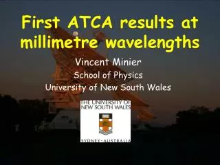
Millimetre Wave and THz Research at QMUL Professor Xiaodong Chen School of Electronic Engineering and Computing Science Queen Mary University of London Email: x.chen@elec.qmul.ac.uk Department of Electronic Engineering
Outline • Where am I from? • History of QMUL Group • Some New Topics • Summary Department of Electronic Engineering
Queen Mary, University of London Queen Mary and Westfield College was founded in 1889, one of four major Colleges of University of London, ranked in12/13 place last year. The newly merged Medical Hospital of the College was founded in 1373, the first teaching hospital in London! Sir Peter Mansfield (Co-winner of 2003 Nobel prize in medicine (MRI)) was a graduate in physics at Queen Mary, University of London. Department of Electronic Engineering
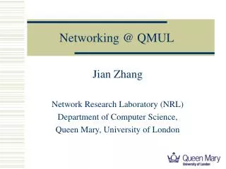
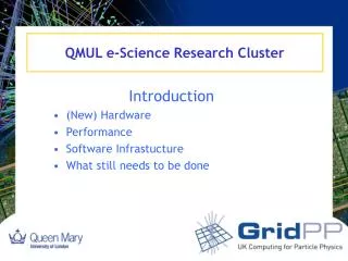
Department of Electronic Engineering Queen Mary, University of London • Antenna & Electromagnetics Group (since 1968) • Networks Group • Centre for Digital Music • Multimedia & Vision Group • 22 full staff + 10 teaching staff Department of Electronic Engineering
The Antenna and Electromagnetic Group • Prof. Clive Parini (Director of Graduate School) • Prof. Xiaodong Chen (Director of Graduate Studies) • Prof. Yang Hao • Dr Robert Donnan (Lecturer) • Dr Akram Alomainy (Lecturer) • Prof Peter Clarricoats, FRS (part time) • Prof. Derek Martin (part time) • Prof. Brian Collins (visiting professor) • George Hockings (visiting professor) • 10 Postdcotoral Research Assistants, • 20 PhD Research Students Department of Electronic Engineering
Brief History: Major Milestones • 1969-70 Analysis and Design of Corrugated Horns. • 1973 First UK Compact Antenna Range. • 1974 First text on Geometric Theory of Diffraction. • 1976 First use of Optimisation in Reflector Antenna Design • 1977 First Design of Array Feeds with Mutual Coupling for Satellite Antennas • 1982 First Design Tools for Shaped-beam Antennas for Spacecraft Applications • 1983 Reflector Surface Metrology using Ultrasound or Millimetrewaves. • 1984 First text on Corrugated Horns. Department of Electronic Engineering
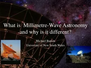
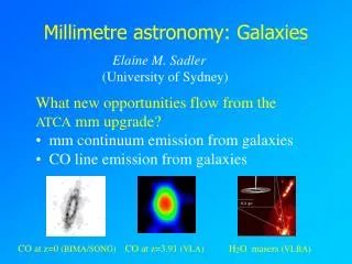
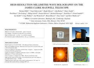
1985:Reflector Design of James Clerk Maxwell Radio Telescope. With a diameter of 15m the James Clerk Maxwell Telescope (JCMT) is the largest astronomical telescope in the world designed specifically to operate in the submillimeter wavelength region of the spectrum. The JCMT is used to study our Solar System, interstellar dust and gas, and distant galaxies. It is situated close to the summit of Mauna Kea, Hawaii, at an altitude of 4092m. Department of Electronic Engineering
1991:200GHz clean room operation of single offset CATR Department of Electronic Engineering
5GHz to 200GHz single offset CATR Department of Electronic Engineering
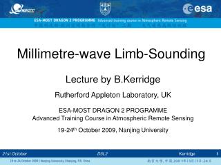
1992: SuccessfulMeasurement ofAdvanced Microwave SoundingUnit -B Department of Electronic Engineering
Mounted on NOAA weather satellite AMSU-B uses passive radiometry to determine upper atmospheric water vapour content 15km 50Km Swath width approx 2000Km Department of Electronic Engineering
530 miles 28.8° Earth rotation Per orbit Orbit plane rotates Eastward 1° per day Orbit covers the globe (except near poles) 2 satellites cover the complete globe in 12 hours Department of Electronic Engineering
AMSU-B channels:- 90GHz 150GHz 183GHz Passive radiometry around the water vapour absorption line (183.3GHz) Department of Electronic Engineering
AMSU-B measured upper atmosphere water vapour content Department of Electronic Engineering
AMSU-B QUASI-OPTICS Mirrors and diochroic plates are used to select the various channels Diochroic plate Input signal Frequency 1 Frequency 2 Department of Electronic Engineering
New Tri-reflector CATR System (2005)Makes efficient use of main reflector Department of Electronic Engineering
300GHz Tri-reflector CATR Demonstrator Currently under test at QM *Spherical Main reflector diameter = 1M *Shaped subreflectors of order 350mm in diameter * rms error on all reflectors about 8 microns * Quiet zone size is 75% of main reflector diameter. * Spherical main reflector permits manufacture of large sizes with 1 micron rms for 1 THz operation using optical mirror technology Department of Electronic Engineering
New Research Topics: • Antenna Technology • Wireless Communications/GPS • EM Healthcare • Quasi-optics and Millimetre Wave • New analysis algorithm –DGBA • Quasi-optical components/system • High Power THz Generation Department of Electronic Engineering
Physical Optics (PO) GTD • Simple • Flexible • Non-singular fields • Ray-based method • Numerically efficient + • Non-modular • caustics • Inefficient for λ << D λ: signal wavelength D: reflector diameter Analysing Qausi-optical system Summary of the ProblemHigh-frequency methods of analysing reflectors Analysis Objective: modular, efficient analysis tool 06/23
} Introducing: DGBA (Diffracted Gaussian Beam Analysis) Modular Analysis Component Structure outputplane diffracted beams } reflector to be analysed reflected beams GB expansion GB expansion diffracted beams Previous reflector input plane
expansion plane 09/23 Gaussian Beam Expansion
Gaussian Beam Reflection reflected beam incident beam: r s r h r x reflected beam: q n h q Gaussian beam optics: x i i s x by Geometrical Optics: incident beam i h “lens formula”: 10/23
d Gaussian beam half screen Gaussian Beam Diffraction- canonical problem - 11/23
Gaussian Beam Diffraction - solution of the canonical problem - : Total diffracted field at the observation point : Unperturbed (incident) field at the observation point : Shadow boundary : Complex phase at the stationary point of the boundary-diffraction integrand : Complex phase at the (first) pole of the boundary-diffraction integrand 12/23
Gaussian Beam Diffraction- normal incidence - P(x,y,z) half screen ^ s s x Q(x ,y ,z ) 0 0 0 w a y 0 z z=-z Gaussian beam amplitude (+1) 0 • Boundary diffraction theory gives asymptotic solution • GO incident beam is complemented by a diffracted field • in terms of complementary error functions • Solution is valid for normal incidence within the paraxial region 13/23
300l shaped shaped 100l 100l feed DGBA test application:A Cassegrain-Gregorian Compact Antenna Range (CATR)– thespherical tri-reflector @ 90 GHz - spherical 16/23
field in the quiet zone (1200l from main reflector) DGBA - Numerical Results- spherical tri-reflector CATR test case - 20/23
Dichroic • Dichroics are well known for their frequency selective characteristics at millimeter and sub-millimeter wave frequencies • There are two basic types of dichroic mirrors: Patch and Slot.
Two channel Quasi-Optical Network (QON) • Two channels: 54GHz (oxygen lines) and 89GHz (atmospheric windows) • High pass dichroic (transmits at 89GHz and reflects at 54GHz) is needed to achieve high pass QO system M1-89 H-89 M1-54 D H-54 M2
High-pass dichroic Porosity value S D High cut-off frequency Low cut-off frequency • The final design: D = 2.16mm, S = 2.46mm, Thickness = 2.5mm
Measurement • Transmission measurement above 75GHz was conducted by placing it in a quasi-optical measurement bench H
Integration of DGBA and PMM Dual Channel Quasi-optical system
M1-54 Horn-54 M2 Integration of DGBA and PMM Results – 54GHz -8.68dB Beamwidth Deg. Simulation.:H-21.51 E-20.92 Measured: H-20.09 E-19.34
M1-89 Dichroic Horn-89 M2 Integration of DGBA and PMM Results – 89GHz -8.68dB Beamwidth Deg. Simulation:H-21.44 E-21.22 Measured:H-19.15 E-19.69
THz sources • One of the most difficult components to realise in sub-millimeter bands is the THz sources. • THz sources can be broadly divided into three categories: • Solid state sources; • Vacuum tube sources; • Optical style sources. • Each of them has its strength and weakness.
Overview: State of the art Gyrotron BWO THz-emission power as a function of frequency Solid line: Conventional THz sources; Ovals: recent THz sources *1: M. Tonouchi, ‘Cutting-edge terahertz technology’, Nature photonics, Feb, 2007
Overview: Physical limitations • Solid state sources: are limited by reactive parasitics, or transit times (RC) rolloff, or heavy resistive losses; • Vacuum tube sources: suffer from physical scaling problem, metallic losses and need for extremely high fields; • Optical style sources: the photon energy level (~meV) too close to that of lattice phonons, needing cryogenic cooling.
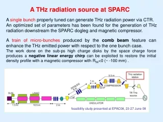
Micro-klystron beam source Experimental measured A-K voltage and current PSD Experimental setup to test the scale down effect
Introduction – What is Pseudo-Spark Discharge? Single gap PSD geometry Paschen curve and pseudospark region • Occurs in special confining geometry • In various gases such as helium, nitrogen, argon, et al • Low pressure, 50-500mtorr, self-sustained, transient hollow cathode discharge, for a gap separation of several mm • High quality electron beam and ion beam extraction before and during the conductive phase
PSD Process • Phase 1: Townsend discharge • - low current pre-discharge • - plasma formation • Phase 2: Hollow cathode discharge • - hollow cathode effect • - plasma expansion • Phase 3: Superdense glow discharge (conductive phase) • - high-current phase (10 kA cm-2 )
Phase 1: Townsend discharge Seed electrons Pre-discharge Plasma formation
Phase 2: Hollow cathode discharge Hollow cathode effect Plasma expansion Secondary emission
Phase 3: Superdense glow discharge Sheath contraction Primary emission Conductive phase
PSD Numerical Simulation MAGIC: Particle-In-Cell and Monte-Carlo Collision (PIC-MCC) Ref: C.K. Birdsall et al, Computer Phy. Comm 87, 1995.
PSD - Gas Ionisation 1. Electron-induced ionisation 2. Ion-induced ionisation The cross section depends on: 1. The energy of the impact electron; 2. The gas type. For different gases, the cross sections are different functions of impact electron energy. The functions can be achieved from experimental results.
PSD-2D Computational Model MAGIC 2D Model: Constant A-K voltage 10kV AK gap d=6mm Radius = 25mm Room temperature Insulator: 6mm thick Perspex Anode aperture: 0.5mm radius Anode thickness: 12mm Cathode aperture: 1.5mm radius Trigger radius: 1mm, cable outer radius: 6mm Nitrogen 100mTorr
PSD-2D Phase 1&2 Plasma formation at 30ns Plasma expansion at 50ns
PSD-2D Phase 3 Plasma expansion and emission at 80ns