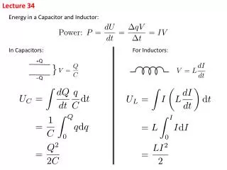
Lecture 26 Ch. 34
160 likes | 344 Views
Physics 2102 Jonathan Dowling. Lecture 26 Ch. 34. Optics: Images — Lenses. Thin Lenses. For small angles and thin lenses,. Convergent lens. Convergent: f positive Divergent: f negative. Divergent lens. Lens maker’s equation. Locating Images by Drawing Rays.

Lecture 26 Ch. 34
E N D
Presentation Transcript
Physics 2102 Jonathan Dowling Lecture 26Ch. 34 Optics: Images — Lenses
Thin Lenses For small angles and thin lenses, Convergent lens Convergent: f positive Divergent: f negative Divergent lens Lens maker’s equation
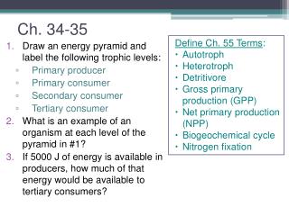
Locating Images by Drawing Rays A ray of direction initially parallel to the axis will pass through the focal point. A ray that initially has a direction that passes through the focal point will emerge parallel to the central axis. A ray going through the center of thelens will be undeflected. The image of a point appears where all rays emanating from a point intersect.
An object placed beyond a convergent lenses’ focal point, will produce a real, inverted image on the other side of the lens. (This is the principle used in movie projectors). • An object placed between a convergent lens and its focal point will produce a virtual image on the same side as the object. (Contact lenses for farsightedness, magnifying glasses.) • Divergent lenses always produce a virtual image on the same side asthe object (Contact lenses for nearsightedness). • Real images have image distance + i, virtual images have –i.
Example • An object 1.2cm high is placed 4cm from a bi-convex lens with r1=10cm and r2=15cm. Find the position and size of the image. • A second lens of focal length +6cm is placed 12cm to the right of the first lens. Find the position and size of the new image.
Example • An object 2cm high is placed 4cm from a bi-convex lens with r1=10cm and r2=15cm, and index of refraction n=1.5. Find the position and size of the image. • A second lens of focal length +6cm is placed 12cm to the right of the first lens. Find the position and size of the new image.
Optical Instruments: the Human Eye The human eye consists of a variable-geometry lens (crystalline) which produces a real image on a “screen” (retina) which is transmitted to the brain via the optical nerve. The cristalline automatically adjusts itself so we see well any object placed between infinity and a distance called “near point” (about 25cm for a typical 20 year old). The “image distance” is the eye diameter~2cm.
F2 F2 Combination of Several (Thin) Lenses: The Microscope F1 F1 If lenses are very close, the compound lens has 1/f~1/f1+1/f2
A nearsighted person needs a divergent lens. Eyeglasses & Contact Lenses A farsighted person needs a convergent lens. The “power” of a lens is measured in dioptres: P=1/f with f is in m. Glasses with -6D are divergent glasses with f=-1/6D =-0.17m=-17cm The dioptres add! Two lenses have 1/f=1/f1+1/f2 D=D1+D2
We’d like to make p smaller (move the object closer). We use a magnifying lens to produce a (larger) image than our eye can see: Very near the focus! Magnifying Lens The magnification of an object is m=i/p=iq/h, but i=eye diameter. Maximum magnification: m~2cm/25cm (!?) Angular magnification (different from lateral): mq=q’/q.
Microscope: To increase the magnification of a lens, one wants to have a short focal length. That means small radii of curvature (very curved lens). This, in turn implies a lot of aberration (one is immediately out of the thin lens approximation). A solution to this is obtained by combining two lenses. The resulting device is called microscope. Object O is magnified by the objective: Total magnification: And its image is magnified by the eyepiece:
Refracting Telescope: Telescopes are arrangement of lenses that improve vision of objects very far away. They are configured like a microscope. However, the objective forms an image essentially at its focus, and therefore the eyepiece’s focus has to be placed at that same point. The magnification is given by the ratio qey/qob, and since Refracting telescopes are of limited use (chromatic aberration). Reflecting telescopes built with mirrors are preferred in astronomy.
Example The world’s largest refracting lens telescope is at the Yerkes Observatory of the University of Chicago at Williams Bay, Wisconsin. (Bigger telescopes use mirrors instead of lenses.) The objective has a diameter of 102cm and a focal length of 19.5m. The focal length of the eyepiece is 10cm. What is its magnifying power? Why so large (102cm)? Because the larger the objective, the more light it gathers.
Reflective Telescopes Keck observatory (Mauna Kea, Hawaii) and the Hale-Bopp comet. Largest optical telescope, composed of 36 (!) hexagonal mirror segments performing as a single mirror 10m wide.