Download
1 / 26
260 likes | 290 Views
Learn about rendering dynamic scenes in real-time using image-based visual hulls. Understand the basics, epipolar geometry, rendering techniques, and system implementation for creating view-dependent visual hulls. Discover future work possibilities and personal opinions on the approach.

E N D
Paper by Wojciech Matusik, Chris Buehler, Ramesh Raskar,Steven J. Gortler and Leonard McMillan [http://graphics.lcs.mit.edu/~wojciech/vh/] Vortrag von Simon Dellenbach GDV Fachseminar 2001 Image-Based Visual Hulls
Overview (1) • Motivation • Basics • Viewpoint Model • Visual Hull • Epipolar Geometry • Creating Image-Based Visual Hulls
Overview (2) • Rendering IBVH • System Implementation • Summary & Results • Future Work • Personal Opinion
Motivation (1) • Traditional computer graphics, rendering.. • static synthetic scenes (CG Images) • dynamic synthetic scenes (CG Animations) • static acquired scenes (Image-Based Rendering) • Acquire and render dynamic scenes in real-time: • appropriate representation • rendering system
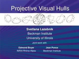
Visual Hull - Basics (2) • Geometric shape obtained using silhouettes of object seen from number of views: • extruded silhouette = cone-like volume limiting the extent of object • intersection of volumes results in a visual hull • more views better approximation of object • limitation: concavities can’t be captured(e.g. an open box looks like a solid cube)
Epipolar Geometry - Basics (4) • The tree points [COP1,COP2,P] form an epipolar plane • Intersection of this plane with image planes results in epipolar lines • The line connecting the two centers of projection [COP1,COP2] intersects the image planes at the conjugate points e1 and e2 which are called epipoles
Creating Image-Based Visual Hulls (1) • Algorithm input: • set of k silhouettes (binary images) with associated viewpoints • desired viewpoint (in this case, constructed visual hull is viewpoint-dependent) • Algorithm output: • sampled image of the visual hull, each pixel containing a list of occupied intervals of space
Creating Image-Based Visual Hulls (2) • The Basic Algorithm: • cast ray into space for each pixel in the desired view of the visual hull • intersect ray with the k silhouette cones k lists of intervals; intersect together single list of intersections of the viewing ray with the visual hull
Creating Image-Based Visual Hulls (4) • Trick: due to Epipolar Geometry interval calculation can be done in image space of reference images: • 3D: intersecting silhouette cone with viewing ray • 2D: intersecting projected viewing ray with silhouette
Rendering IBVH (1) • Reference images are used as textures • For each pixel: • rank reference-image texture from “best” to “worst” according to angle, take reference with lowest • avoid texturing surface points with an image whose line-of-sight is blocked by some other point of the visual hull • consider visibility during shading based on visual hull (not actual geometry)
System Implementation (1) • Four calibrated and triggered digital cameras • One desktop PC per camera for capturing and pre-processing video frames (image segmentation) • Silhouette and texture information sent to central server for IBVH processing
System Implementation (2) • Server runs IBVH intersection and shading algorithms • IBVH objects can be combined with OpenGL background • System runs in ‘real time’ with heavy optimization (like caching strategies for silhouette intersection)
Summary & Results • Use visual hull as object shape approximation • Using silhouette information from reference views to generate view dependent visual hull • Reference images are used as ‘textures’ • Results: Videoclips
Future Work • Find Techniques for blending between textures to produce smoother transitions • Scale up system by using larger number of cameras • Split workload on multiple servers, as algorithm parallelizes fairly much • Speed up viewing ray silhouette intersections (most expensive part of the computation)
Personal Opinion (1) • Pros: • simple technique / low-cost hardware • image-based representation partially compensates simplification problems • epipolar geometry reduces 3D-intersection problems to 2D-intersections
Personal Opinion (2) • Cons: • texture flipping during viewpoint transitions produces ugly results • shadows are considered as part of the object • preprocessing is really expensive(85 ms for image foreground segmentation)
“If there are no questions,there won’t be any answers.” The End ? ? ? ? ? ?