Image-Based Lighting
Image-Based Lighting. © Eirik Holmøyvik . 15-463: Computational Photography Alexei Efros, CMU, Fall 2005. …with a lot of slides donated by Paul Debevec. Inserting Synthetic Objects. Why does this look so bad? Wrong camera orientation Wrong lighting No shadows. Solutions.
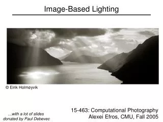

Image-Based Lighting
E N D
Presentation Transcript
Image-Based Lighting © Eirik Holmøyvik 15-463: Computational Photography Alexei Efros, CMU, Fall 2005 …with a lot of slides donated by Paul Debevec
Inserting Synthetic Objects • Why does this look so bad? • Wrong camera orientation • Wrong lighting • No shadows
Solutions • Wrong Camera Orientation • Estimate correct camera orientation and renender object • Use corresponding points to warp the object/scene • Only works for small warps and/or mostly planar objects • Lighting & Shadows • Estimate (eyeball) all the light sources in the scene and simulate it in your virtual rendering • But what happens if lighting is complex? • Extended light sources, mutual illumination, etc.
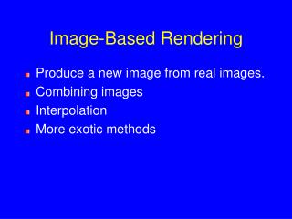
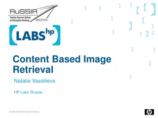
Environment Maps • Simple solution for shiny objects • Models complex lighting as a panoramic image • i.e. amount of radiance coming in from each direction • A plenoptic function!!!
Environment Mapping projector function converts reflection vector (x, y, z) to texture image (u, v) Reflected ray: r=2(n·v)n-v viewer n v r reflective surface environment texture image Texture is transferred in the direction of the reflected ray from the environment map onto the object What is in the map?
What approximations are made? • The map should contain a view of the world with the point of interest on the object as the eye • We can’t store a separate map for each point, so one map is used with the eye at the center of the object • Introduces distortions in the reflection, but we usually don’t notice • Distortions are minimized for a small object in a large room • The object will not reflect itself!
Environment Maps • The environment map may take one of several forms: • Cubic mapping • Spherical mapping • other • Describes the shape of the surface on which the map “resides” • Determines how the map is generated and how it is indexed
Cubic Mapping • The map resides on the surfaces of a cube around the object • Typically, align the faces of the cube with the coordinate axes • To generate the map: • For each face of the cube, render the world from the center of the object with the cube face as the image plane • Rendering can be arbitrarily complex (it’s off-line) • To use the map: • Index the R ray into the correct cube face • Compute texture coordinates
Sphere Mapping • Map lives on a sphere • To generate the map: • Render a spherical panorama from the designed center point • To use the map: • Use the orientation of the R ray to index directly into the sphere
What about real scenes? from Terminator 2
Real environment maps • We can use photographs to capture environment maps • The first use of panoramic mosaics • How do we deal with light sources? Sun, lights, etc? • They are much much brighter than the rest of the enviarnment • User High Dynamic Range photography, of course! • Several ways to acquire environment maps: • Stitching mosaics • Fisheye lens • Mirrored Balls
Stitching HDR mosaics http://www.gregdowning.com/HDRI/stitched/
Scanning Panoramic Cameras • Pros: • very high res (10K x 7K+) • Full sphere in one scan – no stitching • Good dynamic range, some are HDR • Issues: • More expensive • Scans take a while • Companies: Panoscan, Sphereon
Sources of Mirrored Balls • 2-inch chrome balls ~ $20 ea. • McMaster-Carr Supply Companywww.mcmaster.com • 6-12 inch large gazing balls • Baker’s Lawn Ornamentswww.bakerslawnorn.com • Hollow Spheres, 2in – 4in • Dube Juggling Equipmentwww.dube.com • FAQ on www.debevec.org/HDRShop/
0.34 => 59% Reflective Calibrating Mirrored Sphere Reflectivity 0.58
Real-World HDR Lighting Environments FunstonBeach EucalyptusGrove GraceCathedral UffiziGallery Lighting Environments from the Light Probe Image Gallery:http://www.debevec.org/Probes/
Not just shiny… • We have captured a true radiance map • We can treat it as an extended (e.g spherical) light source • Can use Global Illumination to simulate light transport in the scene • So, all objects (not just shiny) can be lighted • What’s the limitation?
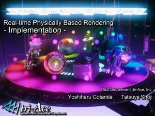
Illumination Results • Rendered with Greg Larson’s RADIANCE • synthetic imaging system
Putting it all together • Synthetic Objects • + • Real light!
Illuminating Objects using Measurements of Real Light Environment assigned “glow” material property inGreg Ward’s RADIANCE system. Light Object http://radsite.lbl.gov/radiance/
Paul Debevec. A Tutorial on Image-Based Lighting. IEEE Computer Graphics and Applications, Jan/Feb 2002.
Rendering with Natural Light SIGGRAPH 98 Electronic Theater