Download

1 / 127
1.28k likes | 1.58k Views
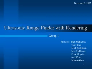
December 9, 2002. Ultrasonic Range Finder with Rendering. Group 1. Members: Matt Mekschun. Tuan Tran. Mark Wilkinson. Max Shikhman. Cory Klopotic. Joel Weber. Matt Anklam. Ultrasonic Range Finder with Rendering I.

E N D
December 9, 2002 Ultrasonic Range Finder with Rendering Group 1 Members: Matt Mekschun Tuan Tran Mark Wilkinson Max Shikhman Cory Klopotic Joel Weber Matt Anklam
Ultrasonic Range Finder with Rendering I • In some applications it is desirable to have a 3-dimensional rendering of a given set of surroundings. Examples of this include security, surveillance, and exploration. • In these types of applications, it is useful to have a low-cost device that can render simple images of the surrounding terrain. • For instance, in a security system it would be beneficial to have real time 3-dimensional data relating to an area being monitored. Augmented with standard video monitoring equipment, a much more meaningful area scan would result. • In low light conditions such as cave exploration, real time 3-dimensional information would be ideal.
Ultrasonic Range Finder with Rendering II • Ultrasonic ranging devices are a simple and inexpensive solution for distance measurements. Used in conjunction with positioning devices, range and position data can be acquired. • At minimum this device should be able to take range, as well as position data, and send it to another device for use in a specific application.
Ultrasonic Range Finder with Rendering III • Ideally, the device should be interfaced to a rendering device (computer), so that a simple, yet useful rendering of the surroundings can be obtained. • Using an RS232 link, position and range data can be transferred serially to a PC. • The acquired data can then be displayed on the PC monitor as a set of 3-dimensional points corresponding to the surrounding terrain.
Project Summarization • Ultrasonic send/receive unit mounted on stepper motors • Allows for 360º lateral scan and ±45º vertical scanning • Optical sensors • Prevent over rotation • Provide starting point • Motor Microcontroller • Initializes and tracks motor motion • Central Microcontroller • Handles user interface • Handles the serial interfacing with the PC, sensor, and other hardware • Calculates Range • 3-D rendering software on a PC • interfaced to the controllers via a serial link.
System Performance Requirements I 120V • Nominal Input Power Sources • Nominal Input Voltage Ranges 5V 5% deviation & 9.6V 10% deviation • Nominal Input Frequency Range 60 Hz • Optical Indicators / Displays Seven (7) Internal LED 20 X 2 Line LCD w/ LED Backlighting 3-D Rendered Image on PC via RS232 • System Inputs Three (3) Momentary Pushbutton (1) Main / Previous Menu (2) Button 1 (3) Button 2 • System Outputs LCD Display & Internal LEDs RS232 DB9 Null-Modem Serial (9600 Bits/S) Two (2) Stepping Motors Ultrasonic Sensor
System Performance Requirements II 5 Volts @ 3 Amp (max) 9.6 Volts @ 1 Amp (max) • Electrical Interfaces Motor mount with internal circuitry enclosure • Mechanical Interfaces Reset Mode Range Mode • Operational Modes Minimum Range: 0.3 (m) Maximum Range: 10.66 (m) Minimum Horizontal Step: 1.8 (degrees) Maximum Horizontal Scan Radius: 360 (degrees) Minimum Vertical Step: 3.6 (degrees) Maximum Vertical Scan Above Horizon: 45 (degrees) Maximum Vertical Scan Below Horizon: 45 (degrees) Range Accuracy: 3 Significant Digits (LCD) 1 Significant Digit (Serial Interface) • Effectiveness
Allocation of Blocks Cory Klopotic Joel Weber Mark Wilkinson Matt Anklam Matt Mekschun Max Shikhman Tuan Tran Block Diagram Pushbutton Interface LCD Master Micro Controller 3D Rendering (PC) Power Conditioning Transmit/Receive Motor Micro Controller Temperature ADC Motor Drivers Stepper Motors Optical Interrupters
Pushbutton Interface Hardware LCD Optical Interrupters Transmit/Receive Stepper Motors Motor Mounts & Enclosure Motor Mounts & Enclosure Allocation of Blocks Cory Klopotic Joel Weber Mark Wilkinson Matt Anklam Matt Mekschun Max Shikhman Tuan Tran
Motor Mount & Enclosure Standard Requirements • Prototype Cost $25 ($135) • Production Cost $10 • Parts Count 9 • Product Size 30x30x40cm (20x20x30cm) • Product Weight 1kg W 2kg (1.5kg) • Power Consumption 0 • Operating Temp Range 0 to 70C (-40 to 126C) • Operating Humidity Range 0 - 100% • Reliability 10 years • Disposal/Recycle Standard Recycling • Safety & Regulatory Standards Enclosure Rating: NEMA 3
Motor Mount & EnclosurePerformance Requirements • Will hold all hardware in a secure, usable fashion. • Includes: motors, optical interrupters, pushbuttons, LCD, circuit boards, and ultrasonic ranger • Be massive enough to keep the base motionless during operation • Allow for 18 wires to be connected without impeding motion of unit • Protect circuit boards from contaminants
Enclosure Wire Hole Optical Interrupter mounting holes Motor Mounting Holes AutoCAD Drawing
Motor 2 Transmitter/Receiver Sensor Mount Motor 1 Motor Mounts Pushbuttons 1.003574 LCD Screen Enclosure AutoCAD Drawing
Motor Mounts& Enclosure AutoCAD Drawing
Production Conceptual Drawing • Molded Plastic Shell • -UHMW Plastic • All parts enclosed • 16x16x20cm AutoCAD Drawing
Allocation of Blocks Matt Anklam Matt Mekschun Temperature Sensor Chip Select 8 Master Micro Controller Temperature ADC Data Bus
Temperature SensorStandard Requirements • Prototype Cost $5 • Parts Count 5 • Product Size 5 x 10 x 3 (cm) • Product Weight 0.01kg • Max Power Consumption 1 (W) • Operating Temp Range 0 - 70 (C) • Operating Humidity Range 0 - 100% (non-condensing) • Reliability 10yrs • Disposal/Recycle Standard Recycling • Safety & Regulatory Standards UL Standard 1310
Temperature SensorPerformance Requirements • Input Active low CS bit • Output 8bits binary Temperature • Sensing Range 0 - 70C° (-17 to 71C°) • Max Return Value Time 50ms (10ms) • Mode of Operation Self Clocking • Chip selected • Resolution 0.5°C/bit • Voh 2.7V • Vol 0.4V • Ioh 4.5mA • Iol -9mA • Must not cause interference on the bus
Temperature Sensor Schematic PSpice Schematic
Temperature Sensor Board Potentiometer used for voltage divider Buffer for Vref/2 LM324A LM34 Analog to Digital Converter 8bit binary output Connected to the data bus ADC0804LCN RC timing components
Description Qty Prototype Production Qty Order # Price Order # Price package Analog to Digital Converter 1 ADC0804LCN 2.60 ADC0804LCWMX 1.26 SOIC 1 Operational Amplifier 1 LM324AN .53 LM324PWR .14 TSSOP 1 56k resistor, 5% 1 CFR-12B-56K .04 ERJ-14YJ563U 04 0603 1 15 turn, 20k potentiometer 1 3006P-1-203 1.73 EVM-2WSX80B24 .42 SMD 1 Temperature Sensor 1 LM34CA .25 LM34CA .25 TO-92 1 .022uf 50V 10% Ceramic Capacitor 1 MC74HC32AN .16 CO603C223K5RACTU .20 TSSOP 1 TOTALS: 6 5.31 2.31 6 Temperature Sensor Parts List
Speed of Sound vs Temperature • Speed of sound is temperature dependent • Vel(ft/s)=1087.2 + 1.968*Temp(ºC) • Distance measurements can vary ±2.5ft (0-40ºC) • Error due to circuit = ±2.16inches
Validation • Measured self clocking frequency (738Hz) • Implemented momentary interrupt • Compared binary temperature to thermometer • Checked operation after circuit integration
Allocation of Blocks Matt Anklam Joel Weber Cory Klopotic Stepper Motors Stepper Motors Motor Drivers Optical Interrupters
Stepper MotorsStandard Requirements • Prototype Cost $25 ($30) • Parts Count 2 • Product Size 5 x 5 x 9 (cm) • Max Product Weight 0.25kg each (0.24kg) • Max Power Consumption 10(W) each (5W) • Operating Temp Range 0 to 70 (ºC) • Operating Humidity range 0-100% (non-condensing) • Reliability 10yrs • Disposal/Recycle Standard Recycling • Safety & Regulatory Standards UL Standard 73
Stepper Motors Performance Requirements • Number of Phases 4 • Number of Leads 6 • Drive System Unipolar • Shaft Length > 2cm • Inductance < 40mH • Resistance < 80 • Power Supply 5-12VDC @ <2.5A • Step Angle < 2 degree step • Holding Torque • XY motor: Greater than 1800g•cm • Z motor: Greater than 800g•cm
Step Angle #Phases Voltage Leads (6) Weight Holding Torque Detent Torque Shaft Length Resistance Inductance 1.8º 4 9.6V AWG26 UL1007 0.24kg 2300gcm 220gcm 2.3cm 75 15mH Motor Diameter Motor Height Price per unit @ Qty=1 Price per unit @ Qty=50 4.32cm 3.56cm $14.95 $11.95 Stepper Motor Characteristics Model: 42BYG205 Wiring Diagram Manufacturer: GBM Bearing Type: Ball Maximum Radial Play: 0.02mm Maximum End Play: 0.1-0.3mm Dielectric Strength: 500V 50Hz/minute Lead wires: 18” Stranded Ambient Temperature Range: -10C To +55C Minimum Insulation Resistance: 100M @ 500VDC Insulation: Class B
Transmit/Receive Ultrasonic Ranging Unit Master Micro Controller Power Conditioning Transmit/Receive Allocation of Blocks Tuan Tran Max Shikhman Matt Mekschun
Transmitter/Receiver-Standard Requirements • Prototype Cost $53.08 • Parts Count 25 parts • Product Size for circuit board 4.52W x 5.64L x 3.81H cm • Product Size for Transducer 4.29D x 0.83H cm • Product Weight 100g • Max Power Consumption 20W • Operating Temp Range 0 – 40 C • Operating Humidity Range 5 – 95 rH% • Storage Temp Range -40 – 70 degree C • Reliability 100% • Safety & Regulatory Standards UL Standard • All parts can be disposed/recycle
Transmitter/Receiver-Performance Requirements • Operating Range 15 – 1070 cm • Accuracy +/-1% Full Scale • Input/Output -Digital -6 wire • Operating Frequency: 50kHz • Operational Modes: -Transmit - Receive - Interrupt • Nominal Input Power Sources 5V DC Power supply • Mechanical Indicator Vibration, “Click”
Transmitter/Receiver-Performance Requirements • Nominal Input/Output Voltages and Current:
Transmitter/Receiver-Methodology • Understood the theory of ultra-sonic sensor • Researched for cheap and reliable sensor • Procured sensor • Bench Test/Troubleshoot • Designed Interface
Transmitter/Receiver -Theory of Operation/Calculation • Speed of sound (air): 343.2meter / second. (@27C) • Speed of sound in millisecond per centimeter: = 1 / Speed of sound = 1 / 343.2m/s = 0.00291 s/m = .0291 ms/cm • Parameters: - Signal Strength (relative to 1/d2) - Humidity (entire range of attenuation, a = 0.01*f dB/m) - Pressure (affect amplitude, uPa ) - Temperature (entire range has a different value of .002ms/cm) • Summary:Signal Strength can be used to calculate the distance of an object away from the source within limited range of temperature and distance.
Transmitter/Receiver -Researched • Type of Ultrasonic Sensors: • - Proximity: detect whether there is an object or not • - Ranging: detect the object and its distance • Type of Ultrasonic Ranging Sensors: • - Electrostatic: • * Behaves like capacitor • * Very sensitive; capable of detecting soft objects; • near and far distances; inexpensive • - Piezo: • * Excites electron • * Less sensitive; work well under harsh environment; • near and far distances; little more expensive
Transmitter/Receiver -Researched • Details of how Electrostatic Ranging Sensor work: • When active, an electrical potential causes the moving plate to attracted to the fix plate. The amount of air between the two plates displaces by the moving plate generates a burst of ultrasonic sound.
Transmitter/Receiver -Procured sensor • Electrostatic transducer is best fit for this design because of its sensitivity and low-cost • Purchased the Polaroid 6500 Sonar Ranging Module Unit • Unit Included: • - Transducer • - Transmitting/Receiving Circuitry
Transmitter/Receiver -Procured sensor • The gain that imitates signal strength of the sensor:
Transmitter/Receiver-Bench Test/Troubleshoot • Test input/output timing • Test accuracy over distances • Adding decoupling capacitor to reduce noise • Ground the BINH and BLNK for single mode operation
Transmitter/Receiver -Designed Interface • Inverted input signal • Inverted output signal
Description Prototype Production Part Number Cost Package Cost Qty Polaroid 6500 Electrostatic Ranging Board R11-6500 $52.30 N/A $49.69 1 Resistor, 5%, 1/4W, 1k-Ohm 4.7kQBK-ND $0.02 N/A $0.02 1 Quad NAND Gate 74HCT00 $0.28 SOT108-1 $0.91 1 Capacitor, 20%, 50V, 1uF, Ceramic BC1133CT-ND $0.48 N/A $0.48 1 Transmitter/Receiver Parts Description
Allocation of Blocks Matt Mekschun PC Rendering 3D Rendering (PC) Master Micro Controller
PC Rendering Software - Purpose • The primary tasks for the rendering software block are as follows: • Receive a 6-byte encoded data packet from the ranging hardware device via the serial port. • Verify the data packet, then decode the position and range information from it. • Use the position and range data to create a point in 3-D space using the OpenGL graphics API.