
Comprehensive Overview of VLSI Test Pattern Generation Methods
E N D
Presentation Transcript
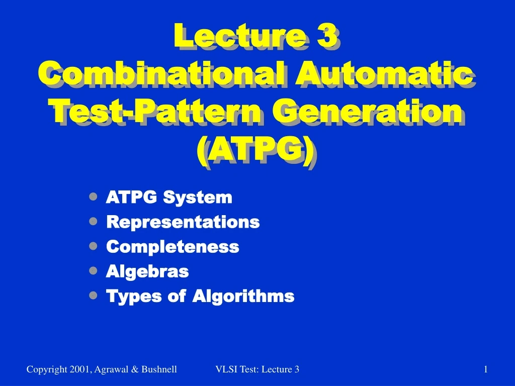
Lecture 3Combinational Automatic Test-Pattern Generation (ATPG) • ATPG System • Representations • Completeness • Algebras • Types of Algorithms VLSI Test: Lecture 3
ATPG Problem • ATPG: Automatic test pattern generation • Given • A circuit (usually at gate-level) • A fault model (usually stuck-at type) • Find • A set of input vectors to detect all modeled faults. • Core problem: Find a test vector for a given fault. • Combine the “core solution” with a fault simulator into an ATPG system. VLSI Test: Lecture 3
What is Test? Fault activation Fault effect X 1 0 0 1 0 1 X X Combinational circuit 1/0 1/0 Primary inputs (PI) Primary outputs (PO) Path sensitization Stuck-at-0 fault VLSI Test: Lecture 3
ATPG is a Search Problem • Search the input vector space for a test: • Initialize all signals to unknown (X) state – complete vector space is the playing field • Activate the given fault and sensitize a path to a PO – narrow down to one or more tests Vector Space Vector Space Circuit Circuit X X X X 0 1 0/1 sa1 sa1 001 101 VLSI Test: Lecture 3
Need to Deal With Two Copies of the Circuit Good circuit X X 0 1 Alternatively, use a multi-valued algebra of signal values for both good and faulty circuits. 0 Same input Different outputs Circuit Faulty circuit X X 0 1 X X 0 1 0/1 sa1 1 sa1 VLSI Test: Lecture 3
Circuit and Binary Decision Tree VLSI Test: Lecture 3
Binary Decision Diagram • BDD – Follow path from source to sink node – product of literals along path gives Boolean value at sink • Rightmost path: A B C = 1 • Problem: Size varies greatly with variable order VLSI Test: Lecture 3
Algorithm Completeness • Definition: Algorithm is complete if it ultimately can search entire binary decision tree, as needed, to generate a test • Untestable fault – no test for it even after entire tree searched • Combinational circuits only – untestable faults are redundant, showing the presence of unnecessary hardware VLSI Test: Lecture 3
Algebras: Roth’s 5-Valued and Muth’s 9-Valued Fault-free circuit 1 0 0 1 X 0 1 X X Alternative Representation 1/0 0/1 0/0 1/1 X/X 0/X 1/X X/0 X/1 Faulty Circuit 0 1 0 1 X X X 0 1 Symbol D D 0 1 X G0 G1 F0 F1 Roth’s Algebra Muth’s Additions VLSI Test: Lecture 3
Roth’s and Muth’s Higher-Order Algebras • Represent two machines, which are simulated simultaneously by a computer program: • Good circuit machine (1st value) • Bad circuit machine (2nd value) • Better to represent both in the algebra: • Need only 1 pass of ATPG to solve both • Good machine values that preclude bad machine values become obvious sooner & vice versa • Needed for complete ATPG: • Combinational: Multi-path sensitization, Roth Algebra • Sequential: Muth Algebra -- good and bad machines may have different initial values due to fault VLSI Test: Lecture 3
D D D D D D Function of NAND Gate D 1/0 0/1 a b 1 c Input b VLSI Test: Lecture 3
Exhaustive Algorithm • For n-input circuit, generate all 2n input patterns • Infeasible, unless circuit is partitioned into cones of logic, with 15 inputs • Perform exhaustive ATPG for each cone • Misses faults that require specific activation patterns for multiple cones to be tested VLSI Test: Lecture 3
Random-Pattern Generation • Flow chart for method • Use to get tests for 60-80% of faults, then switch to D-algorithm or other ATPG for rest VLSI Test: Lecture 3
Boolean Difference Symbolic Method (Sellers et al.) g = G (X1, X2, …, Xn) for the fault site fj = Fj (g, X1, X2, …, Xn) 1 jm Xi = 0 or 1 for 1 in VLSI Test: Lecture 3
Boolean Difference (Sellers, Hsiao, Bearnson) • Shannon’s Expansion Theorem: F (X1, X2, …, Xn) = X2F (X1, 1, …, Xn) + X2F (X1, 0, …, Xn) • Boolean Difference (partial derivative): Fj g • Fault Detection Requirements: G (X1, X2, …, Xn) = 1 Fj g = Fj (1, X1, X2, …, Xn) Fj (0, X1, …, Xn) = Fj (1, X1, X2, …, Xn) Fj (0, X1, …, Xn) = 1 VLSI Test: Lecture 3
Path Sensitization Method Circuit Example • Fault Sensitization • Fault Propagation • Line Justification VLSI Test: Lecture 3
Path Sensitization Method Circuit Example • Try path f – h – k – L blocked at j, since there is no way to justify the 1 on i 1 D D D D 1 D 0 1 1 VLSI Test: Lecture 3
Path Sensitization Method Circuit Example • Try simultaneous paths f – h – k – L and g – i – j – k – L blocked at k because D-frontier (chain of D or D) disappears 1 D D 1 1 D D D 1 VLSI Test: Lecture 3
Path Sensitization Method Circuit Example • Final try: pathg – i – j – k – L – test found! 0 0 D D 1 D D D 1 1 VLSI Test: Lecture 3
Forward Implication • Results in logic gate inputs that are significantly labeled so that output is uniquely determined • AND gate forward implication table: VLSI Test: Lecture 3
Backward Implication • Unique determination of all gate inputs when the gate output and some of the inputs are given VLSI Test: Lecture 3
Implication Stack • Push-down stack. Records: • Each signal set in circuit by ATPG • Whether alternate signal value already tried • Portion of binary search tree already searched VLSI Test: Lecture 3
B B E F F F Implication Stack after Backtrack Unexplored Present Assignment Searched and Infeasible 0 1 0 0 1 1 1 0 1 0 0 1 VLSI Test: Lecture 3
Objectives and Backtracing of ATPG Algorithm • Objective – desired signal value goal for ATPG • Guides it away from infeasible/hard solutions • Backtrace – Determines which primary input and value to set to achieve objective • Use testability measures VLSI Test: Lecture 3
Branch-and-Bound Search • Efficiently searches binary search tree • Branching – At each tree level, selects which input variable to set to what value • Bounding – Avoids exploring large tree portions by artificially restricting search decision choices • Complete exploration is impractical • Uses heuristics VLSI Test: Lecture 3