Download
1 / 29
290 likes | 427 Views
Explore how binary code is used to create images and sound representations, including data representation, bitmap display, color coding, and digitized images and graphics.

E N D
Video on Image and Sound • The following link is a video on how binary code is used to create images and sound https://www.youtube.com/watch?v=pmY7pOQCOr8
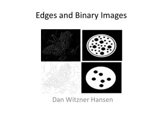
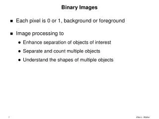
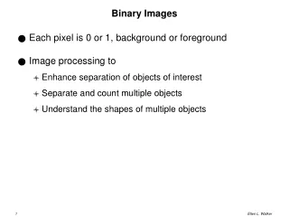
Data Representation • Not all data can be represented as characters. • To process images and soundin a computer, they must be represented as binary codes. • An imagecan be represented as a map of binary codes • If the image is zoomed, the individual pixels can be seen as either black or white. • In a black and white image, only 1 Bit is needed to represent each pixel as the pixel can only be black or white.
10x9 bit grid for this image. • Each square represents 1 bit or 1 pixel, therefore this grid represents 90 pixels
You tube video on images • https://www.youtube.com/watch?v=uaV2RuAJTjQ
Assignment • Work on the binary imaging handout
Data Representation This is called a Bitmapped image as the bits used to represent the image are arranged into a grid of Bits A more complex image is shown to the right and the grid and map of Bits is clearly visible The only difference between this and a colour image is the number of Bits needed to represent each pixel In 24-bit colour, 24 Bits are needed for each pixel etc This small section may be based on a 24 x 24 bit grid.
How many pixels should be used • If too few pixels are used, image appears “coarse” 16 x16 (256 pixels) 64 x 64 (4096 pixels)
Bitmap Display • Monochrome: black or white • 1 bit per pixel • Gray scale: black, white or 254 shades of gray • 1 byte per pixel • Colourgraphics: 16 colours, 256 colours, or 24-bit true colour(16.7 million colours) • 4, 8, and 24 bits respectively; • This is equivalent to ½ byte, 1 byte and 3 bytes • An RGB value of (255, 255, 0) maximizes the contribution of redand green, and minimizes the contribution of blue, which results in a bright yellow
Representing Images and Graphics • A color palette is a set of colors, for example • Colors supported by a monitor • Web-safe colors for use with Internet browsers • Colors from which user can choose • Colors used in an image
Digitized Images and Graphics • Pixels (picture elements) • Dots of color in image (or display device) • Resolution • Number of pixels in image (or device) • Raster Graphics • Treat image as collection of pixels • Most common formats: BMP, GIF, PNG, and JPEG • Vector Graphics • Treat image as collection of geometric objects • Most important formats: Flash and SVG
Digitized Images and Graphics • BMP (bitmap) • TrueColor color depth, or less to reduce file size • Well suited for compression by run-length encoding • GIF (indexed color) • File explicitly includes palette of 256 or fewer colors • Each pixel thus requires only 8 or fewer bits • Animated GIFs are short sequences of images
Digitized Images and Graphics • PNG (Portable Network Graphics) • Intended to replace GIFs • Greater compression with wider range of color depths • No animation • JPEG(Joint Photographic Experts Group) • Averages hues over short distances • Why? Human vision tends to blur colors together within small areas (science!) • Adjustable degree of compression
Digitized Images and Graphics Whole picture A digitized picture composed of many individual pixels
Digitized Images and Graphics Magnified portion of the picture See the pixels? Each pixel of the image now fills ablock of screenpixels
Colour Coding • RED COLOUR = R: 255 G:0 B:0 = 11111111 00000000 00000000 • Green Colour = R: 0 G:255 B:0 = 00000000 11111111 00000000 • Blue Colour= R: 0 G:0 B:255 =00000000 00000000 11111111 • Yellow Colour = R: 255 G:255 B:0 = 11111111 11111111 00000000 • Cyan Colour = R: 0 G:255 B:255 = 00000000 11111111 11111111 • Noticethatthere are 3 decimalvaluesofRed Green and Blue. • This equates to 3 bytes (24 bits) of information to create colour. • This is also a 6 value hexadecimal colour code.
Colour Coding in Hexadecimal • Nowone byte ofinformationisequal to a 2 – digithexadecimalnumber. • R:180G:39B:189 (180, 39, 189) • In hexadecimal that would be converted to • R:b4G:27B:bd (b4, 27, bd) • This colour code of b4, 27, bd is a purple colour.
RGB, COLOUR in Binary Code • Use the Binary Text/Image/Sounds handout and discuss the images section of it. • Use the encoding images handout to show how the website on the next slide works.
Imagine the fun of images • Black and White Pixels Version 1 – you are to make a basic image using 1’s and 0’s. • http://cs.ucls.uchicago.edu/~bfranke/codeDotOrg/Pixelation/Pixelation_v1.html • Black and White Pixels Version 2 • http://cs.ucls.uchicago.edu/~bfranke/codeDotOrg/Pixelation/Pixelation_v2.html • ColourPixels, Version 3 • http://cs.ucls.uchicago.edu/~bfranke/codeDotOrg/Pixelation/Pixelation_v3.html
Assignment • 1. Using Version #1 - http://cs.ucls.uchicago.edu/~bfranke/codeDotOrg/Pixelation/Pixelation_v1.html • Draw on the computer either a) the tea cup, b) The image of Saturn, or c) The image of the face. • 2. Use Version #2 - http://cs.ucls.uchicago.edu/~bfranke/codeDotOrg/Pixelation/Pixelation_v2.html • Identify how to create a grid in binary code • Draw an image in pixels on your graphing paper • Redraw the image using version 2 software
3. Use Version#3 - http://cs.ucls.uchicago.edu/~bfranke/codeDotOrg/Pixelation/Pixelation_v3.html • Do the exact same thing as in question #2. This time make the image a colour image. Use photoshop to help assist in the making of different colours.
Sound in Binary Code • Recall this image from our sound card. • The values along the y axis are decimal numbers.
How we convert analog sound to binary code • So, we sample 48,000 times per second. • The vertical range of magnitudes is sampled into 256 levels (8 bit) or 65536 levels (16 bit) or, most accurately, about 16 million levels (24 bit). • For each sample point we now have a number, and the whole audio signal is no more than a sequence of numbers. Take these numbers and convert them to binary.
How we convert analog sound to binary code • In the following figure, let's assume that the sampling rate is 1,000 per second and the precision is 10: The green rectangles represent samples. Every one-thousandth of a second, the ADC looks at the wave and picks the closest number between 0 and 9.
How we convert analog sound to binary code • The number chosen is shown along the bottom of the figure. • These numbers are a digital representation of the original wave. • Digital reading: 7 8 9 • Binary form: 111 1000 1001
You can see that the blue line lost quite a bit of the detail originally found in the red line, and that means the fidelity of the reproduced wave is not very good. This is the sampling error. You reduce sampling error by increasing both the sampling rate and the precision When the DAC recreates the wave from these numbers, you get the blue line shown in the following figure:
In these diagrams the rate and the precision have been improved
Digital Sound Both images are the same data of an analog sound converted into a digital sound. The key here is how the first image has the y axis in numbers, and the second image has the exact same values, but it is written in binary code.
Digital Sound • Identify the binary code of this analogue sound wave that has passed through an ADC in the computer at: • 1 second • 3 seconds • 5 seconds • 7 seconds