Download
1 / 44
440 likes | 464 Views
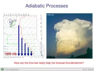
Explore the research on resonant power drivers and adiabatic logic presented by Michael P. Frank in October 2006. Discover the motivation behind developing energy-recovering logic in CMOS and quantum-dot cell automata. Learn about the potential of Quantum-Dot Cell Automata (QCA) and its applications, such as functional completeness, QCA full adder module, and more complex circuit designs. Dive into the fabrication processes and potential molecular QCA implementations, including IBM/Columbia resonant clocks and High-Q MEMS resonators at U. Mich. Explore innovative concepts like the Rotary Clock and the Trapezoidal MEMS resonator for efficient energy use. Witness the advancements in adiabatic logic and resonant clock technologies showcased in this comprehensive research overview by M. Frank.

E N D
Design & Analysis of Resonant Power/Clock Drivers for Adiabatic Logic Research Overview Michael P. Frank Thursday, October 5, 2006 (Presented to S. Foo, H. Li, J. Zheng) M. Frank, Research Presentation, Oct. 2006
Outline • Motivation • Device & architectural work • Analog circuit analysis M. Frank, Research Presentation, Oct. 2006
Motivation • Logic performance is increasingly limited by power dissipation constraints, with unfortunate results… • Over the last few years, clock speeds have been increasing rather more slowly than in the past (19%/yr instead of 58%/yr) • The energy efficiency of traditional digital switching schemes is approaching fundamental thermodynamic limits: • Today: Switching a min-size FET dissipates ~200 eV • ~1 eV dissipation/switching event for any reliable FET-based techology • ~18 meV (kT ln 2) for any irreversible technology • To beat these limits will require an increasing amount of energy recovery in switching • Several types of logic devices that allow this are known M. Frank, Research Presentation, Oct. 2006
Energy-Recovering Logic in CMOS • Basic idea: Still use ordinary CMOS transistors, but switch their state adiabatically • Gradually, with less dissipation (see later analysis) • We now know how to build fully-adiabatic versions of arbitrary combinational and sequential logic • One requirement: Fully adiabatic switching events must also be logically reversible • Perform an invertible transformation of the digital state • Problem with CMOS: Energy coefficient Q2R is relatively large, results in low cost-performance M. Frank, Research Presentation, Oct. 2006
Another Adiabatically Switchable Device: The Quantum-Dot Cell • Group several quantum dotsclose together into a “cell” • Separated by tunnel junctions • Excess electrons in the celloccupy certain naturally-stable configurations • E.g. 2 electrons will tend to settle in opposite corners due to Coulombic repulsion • By electrostatic biasing we can adiabatically restore the cell to a neutral polarization • From which it may be easily induced to switch to either state M. Frank, Research Presentation, Oct. 2006
Quantum-Dot Cell Automata “wire” • Line of neighboring cells are driven in sequence • Each cell is biased by the neighboring cell to take on the same state as its neighbor • Flow of information along wires can be wave-pipelined M. Frank, Research Presentation, Oct. 2006
Doing logic with quantum-dot cells • With a different arrangement of cells, we can complement the input signal a=0 q=1 M. Frank, Research Presentation, Oct. 2006
Functional completeness • This assemblage of cells implements the majority function • q = MAJ(a,b,c) = ab + ac + bc • Using MAJ, we can do AND and OR, and thus (with NOT) compute anything… a=0 b=0 q=0 c=1 M. Frank, Research Presentation, Oct. 2006
QCA Full Adder Module M. Frank, Research Presentation, Oct. 2006
A more complex circuit M. Frank, Research Presentation, Oct. 2006
One potential fabrication process M. Frank, Research Presentation, Oct. 2006
QCA structures fabricated at Sandia • The surface is a SiGe single crystal film on a Si (001) substrate. • The square structures are monolithic groupings of four self-assembled SiGe dots surrounding a central pit in the film (which elastically binds the 4 dots). • The lateral dimension across each of the structures is about 250 nm – • larger than a potential production device, but small enough to demonstrate the relevant behavior. • Placement of the four-dot cells into specific geometric arrangements needed for QCA is accomplished using a Focused Ion Beam (FIB) to create preferred nucleation sites. M. Frank, Research Presentation, Oct. 2006
Potential Molecular QCA Implementation • Would work at room temperature due to small dot separation and high (~eV) barrier energies • Synthesis of molecules and quantum chemistry simulations of electron behavior has been completed • Challenge is to arrange molecules at precise locations on a surface M. Frank, Research Presentation, Oct. 2006
IBM/Columbia Resonant Clocks M. Frank, Research Presentation, Oct. 2006
MultiGig’s “Rotary Clock” M. Frank, Research Presentation, Oct. 2006
High-Q MEMS Resonators at U. Mich M. Frank, Research Presentation, Oct. 2006
Moving metal plate support arm/electrode Moving plate Range of Motion Trapezoidal MEMS Resonator Concept Arm anchored to nodal points of fixed-fixed beam flexures,located a little ways away, in both directions (for symmetry) … z y Phase 180° electrode Phase 0° electrode Repeatinterdigitatedstructurearbitrarily manytimes along y axis,all anchored to the same flexure x C(θ) C(θ) 0° 360° 0° 360° θ θ (PATENT PENDING, UNIVERSITY OF FLORIDA) M. Frank, Research Presentation, Oct. 2006
A Manufacturable Approximation (Earlydesignw. thinfingers) Four-finger sensor Capacitance Simulated Output Waveform (PATENT PENDING, UNIVERSITY OF FLORIDA) M. Frank, Research Presentation, Oct. 2006
Partially Fabbed Prototype • Post-etch process was still being fine-tuned. • Parts were not yet ready for testing… • and then the funding ran out. Primaryflexure(fin) Sensecomb Drive comb M. Frank, Research Presentation, Oct. 2006
Clock Distribution Network Design by M. Ottavi at Sandia, In Progress M. Frank, Research Presentation, Oct. 2006
The Present Effort • A wide variety of resonator design techniques are presently being explored… • Each different resonator approach naturally delivers a given shape of voltage waveform • We want to more carefully analyze and understand the interplay between: • resonator design, • waveform shape, • and the energy efficiency of adiabatic charge transfers in the logic M. Frank, Research Presentation, Oct. 2006
Initial Circuit Model for Analysis • Basic lumped-element RC circuit model. M. Frank, Research Presentation, Oct. 2006
General Waveform Model M. Frank, Research Presentation, Oct. 2006
Cumulative Energy Transferred τ1 Esup Erec Ed,tr Etfr Ed,cyc τ0 Egap M. Frank, Research Presentation, Oct. 2006
Energy Flow Summary = CV2/2 =QtfrVgap M. Frank, Research Presentation, Oct. 2006
Energy Efficiency Metrics • Energy transfer efficiency: • Energy transferred to the load, per unit of energy dissipated in that transition • Range is [0, ∞) • Energy recovery efficiency: • The fraction of energy supplied from the source terminal during charging that is later returned to the source terminal • Range is [0, 1) • Resonant quality factor: • Ratio between energy supplied by the source in charging and energy dissipated per cycle • Range is [1, ∞) • Other related metrics could be defined M. Frank, Research Presentation, Oct. 2006
Relations Between the Metrics • The energy transfer efficiency, energy recovery efficiency, and quality factor are related to each other by: M. Frank, Research Presentation, Oct. 2006
Particular Wave Shapes Analyzed • Step function • Zero-frequency limit of square wave • Square wave (arbitrary frequency) • Linear ramp (arbitrary rise time) • Truncated by flat wave top • Zero-frequency limit of trapezoidal wave • Trapezoidal wave (arb. rise time & frequency) • Sinusoidal wave (arbitrary frequency) M. Frank, Research Presentation, Oct. 2006
Step Function Results • Energy transfer efficiency is exactly 1. • Exactly the same amount of energy (CV2/2) is dissipated in each transition as is transferred onto or off of the load • The energy recovery efficiency is exactly 0. • Lowest possible. CV2 supplied, 0 recovered. • The quality factor is exactly 1. • The lowest possible, given that all energy dissipated ultimately comes from the source M. Frank, Research Presentation, Oct. 2006
General Square Wave Response M. Frank, Research Presentation, Oct. 2006
Cumulative Energy Transfers for the Example Square Wave Ed,tr Esup Ed,cyc Etfr Egap τ0 τ1 M. Frank, Research Presentation, Oct. 2006
Results for Square Wave • Energy transfer efficiency is <1: • Energy recovery efficiency is still 0. • And Q is still 1. M. Frank, Research Presentation, Oct. 2006
Energy Transfer Inefficiency of Square Wave Driver as a function of Frequency M. Frank, Research Presentation, Oct. 2006
Energy Transfer Efficiency of the Linear Ramp Driver • Energy transfer efficiency is >1: • with r = RC/τ (τ = rise time), and ε = 1/r = τ/RC. • Clearly approaches 1 asτ → 0 (step function) M. Frank, Research Presentation, Oct. 2006
Energy Transfer Inefficiency of Linear Ramp Driver as a Function of Rise Time M. Frank, Research Presentation, Oct. 2006
Energy Recovery Efficiency for Linear Ramp Driver • Has both upper and lower bounds… M. Frank, Research Presentation, Oct. 2006
Energy Recovery Efficiencyof the Linear Ramp Driver M. Frank, Research Presentation, Oct. 2006
Trapezoidal waveform example M. Frank, Research Presentation, Oct. 2006
Still to do: Analysis of Trapezoidal Wave • Need to determine load voltage range V as a function of the source voltage range Vs and the wave parameters τrise and τcyc. • Then calculate Esup, Ed,tr, and Etfr for this case… • Then calculate the energy efficiencies… • Also, for a given value of τcyc, what value of τrise gives the best efficiency? • It may turn out to be a constant fraction of τcyc. M. Frank, Research Presentation, Oct. 2006
Analysis of the Sinusoidal Driver • Load voltage amplitude is given by • Energy transferred onto the load is thus • Meanwhile, the energy dissipated per transition is M. Frank, Research Presentation, Oct. 2006
Energy Transfer Efficiency of the Sinusoidal Driver • Energy transfer efficiency is: • Exactly equal to the cycle period divided by the characteristic time tc = π2RC/2 ≈ 4.93RC. M. Frank, Research Presentation, Oct. 2006
Energy Supplied by theSinusoidal Driver During Charging • Present form, needs more simplification… • Then find Erec by subtracting 2Ed,tr… • Then we are in a position to calculate ηE,tr… M. Frank, Research Presentation, Oct. 2006
Final steps for sinusoidal driver… • How do the energy transfer and recovery efficiencies of the sinusoidal wave compare to those of the (optimized) trapezoidal wave? • There may turn out to be just a constant factor difference in efficiencies between the two cases… • Which wave shape is more efficient at finite frequencies? Does the choice of which is better depend on the value of RCf? M. Frank, Research Presentation, Oct. 2006
Ideas for Follow-on Work • Do a variational analysis in terms of stationary functionals to find the exact source wave shape that maximizes energy efficiency, in terms of given values of the relative cycle period τcyc/RC and the load voltage swing V. • Borrow methods used to calculate least-action trajectories in physics • Elaborate the circuit model into some more realistic, representative models of particular resonator and clock distribution circuits • Do a systems-engineering type optimization of resonator designs together with particular classes of logic devices M. Frank, Research Presentation, Oct. 2006