Download
1 / 30
300 likes | 541 Views
A framework for integrated process monitoring in grinding machine control. John Moruzzi GERI / AMTReL. M. N. Morgan, X. Chen , D.R. Allanson. Introduction.

E N D
A framework for integrated process monitoring in grinding machine control John Moruzzi GERI / AMTReL M. N. Morgan, X. Chen, D.R. Allanson A framework for integrated process monitoring in grinding machine control
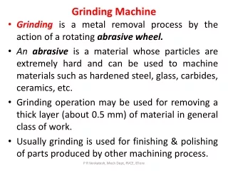
Introduction In machining, and particularly grinding, it is desirable to have a control system that can integrate and adopt the latest Process Control and Monitoring equipment, and implement enhanced production cycles. Grinding optimization technologies include wheel balancing, in-process gauging, touch detection (power and acoustic emission) and other sensor-based strategies. A selection of such features may be included in higher-end grinding machines in response to specific requirements, however this involves significant customisation and application engineering from the machine builder. It is often impractical or uneconomic to apply the benefits of this technology to simpler, cheaper grinding machines, despite the fact that low-cost process control equipment is becoming increasingly available. A framework for integrated process monitoring in grinding machine control
Objectives and Innovation An innovative new software-based design strategy is therefore proposed to directly address the issue of improved process control integration. The aim is to unify the design and implementation of key machine tool features such as hardware configuration parameters, operational parameters, process variables and machining cycles into a rationalized, extendable, Object-Oriented framework suitable for implementation using current PC hardware and software. In order to implement such a framework it is necessary to identify and specify the keyfeatures of the new system, using a standardized format that will allow similarities and synergies to be recognised and optimised. The main items for consideration are: • Cycles and Part programmes (Grinding, Dressing, Balancing) • Hardware features (Connectors,Interfaces) • Communication features (Protocols, data structures) • Operational features (Functions, signals, data) • Software features (Configuration, displays) A framework for integrated process monitoring in grinding machine control
Control of the grinding process Automatic Plunge Cycle A BASIC GRINDING CYCLE: The fundamental process parameters for grinding cycles are wheel and workpiece speed. Additionally there will be defined various infeed rates, infeed setpoints (Coarse, Medium, Fine, Final size), reversal points (Left and Right) and time dwells. The machine control will execute a sequence of moves to the programmed axis positions at the appropriate speeds, and the expectation is that a satisfactory part will be produced. A typical automated cycle path is shown : A framework for integrated process monitoring in grinding machine control
Monitoring of the grinding process • Key target functions: • Wheel Balancing (vibration sensing / correction) • Touch Detection (Acoustic Emission or Power sensing) • Gauging (Size / Position measurement) • Auxiliary Process Monitoring equipment is generally a stand-alone unit, connected to the machine control via a wiring or communications interface. The operator will set the device operating parameters and monitor its behaviour via a control panel. • As various programmed conditions are met during machining, appropriate signals and visual indications are set by the device. The operator or machine control will then respond to this information according to a defined strategy. • The devices will generally operate in Manual mode (operator control) or Automatic mode (machine control). The enhanced system is designed to accommodate fuller integration of process monitoring equipment with the machine control system. A framework for integrated process monitoring in grinding machine control
Quality Issues In practice the physical variability of the process, such as wheel wear, machine deflections, and temperature variations mean that adjustments to the grinding parameters need to be made in order to improve the quality of the finished part . The refinements to the process variables are often made in response to changes in the part dimensions, surface finish or roundness, and are identified through post-process measurements and operator experience. A framework for integrated process monitoring in grinding machine control
Efficiency Issues • Key process efficiency issues: • Optimisation of machining and dressing times • Reduction in scrap, reworking, replacement of wheels etc. A framework for integrated process monitoring in grinding machine control
Safety Issues • Key process safety issues: • Protection of operator from crash or failure conditions • Reduction in machine, wheel and part damage A framework for integrated process monitoring in grinding machine control
Example Arrangement of Integrated System CNC MAIN CONTROL A framework for integrated process monitoring in grinding machine control
Major equipment suppliers Challenges leading to the development of a generic type interface: • Lack of standardisation between CNC and equipment manufacturers • Different interfacing hardware and strategies for Process Control equipment. • Different levels of functionality / complexity A framework for integrated process monitoring in grinding machine control
Machine Control and Balancer features Functional similarities between equipment types: The wheel balancer can be seen as a simplified version of a machine control system. The fundamental features, functions, quantities and interfaces in a typical grinding machine control are shown below. A framework for integrated process monitoring in grinding machine control
Gauge and Touch Detector features There are also similarities in the functionality of the Gauging and Touch Detector features. Both use various sensors and channels to monitor and control different phases of the grinding cycle. They will use different cycle parameters for machining different parts. A framework for integrated process monitoring in grinding machine control
CNC Equipment Interfacing CNC main module Bus System devices are interconnected to transmit and exchange: • Control signals • Status signals • Process data • Configuration data Digital IO CNC axis drives Analog Ethernet Ethernet Bus PC unit Profibus RS232 Digital IO Bus Digital IO Monitoring unit CNC IO modules A framework for integrated process monitoring in grinding machine control
Equipment interfacing schemes Main schemes for interaction between devices: Digital I/O Interface (Conventional) 24V DC opto-isolated digital inputs and outputs. Each line set to 0 or 24V level = Low / High, On / Off, True / False. Serial communications interface (RS232, USB) Traditional method between computer hardware. Direct Port-Port connection. Bus / Fieldbus communications (Profibus, Modbus, Interbus,…) RS 485-based. Devices daisy-chained together : 1 x Master, n x slaves (with ID) Network communications (Profinet, DeviceNet,…) Ethernet / TCPIP based. A framework for integrated process monitoring in grinding machine control
Dittel M5000 TD unit - signals definition IO Interface table Describes the connector hardware and pin / line assignments. Identifies input and output lines and numbers. Identifies power supply/ ground lines. Describes logic levels (sense of signal) Describes signal wiring (Source / Sink) A framework for integrated process monitoring in grinding machine control
BS VM9 TD unit - signals definition IO Interface table - 2 Equivalent table for similar Touch Detector unit from a different supplier. Small set of names and descriptors helps to identify common or similar features. Formalised / standardised structure aids device analysis and documentation. A framework for integrated process monitoring in grinding machine control
Key interactions with devices What we would like our system to do… • Main actions : • Device configuration • Device operation • Device monitoring • Main data: • Control, status and alarm signals • Process signal values • Device parameters A framework for integrated process monitoring in grinding machine control
Objectives for Open Control Systems: The new system builds on the Open Control Systems concept, originating in the 1990s for Machine Tool Control applications: • Commercial or Industry standard hardware (increasingly moving in this direction) • Modular software structures (now commonplace) • Well defined software interfaces - standardised • Vendor-neutral architectures and application modules • Flexible and reconfigurable , adaptable to new technologies and processes • Layered approach to structure hides hardware-specific features A framework for integrated process monitoring in grinding machine control
Open Control Systems : previous work OSACA / OSACA II (1992, 1997 ESPRITIII) Open Systems Architecture for Controls in Automation Systems Participants: Num, Fagor, Bosch, Siemens, Comau, Uni.Stuttgart & Aachen OCEAN (2002 Framework 5) Open Controller Enabled by an Advanced real-time Network Participants: Homag, Fagor, OSAI, Fidia, Uni.Stuttgart & Aachen OROCOS (2000 …) Open RObot COntrol Software Participants: Uni. Leuven & Collaborators (Laas, KTH, LVD, Flanders Mechatronics) OCI (1997) Open Control Interface Statham (LJMU AMTReL) Outcomes: Basic outcomes published but no recognised standards adopted. Further developments kept “in-house” or public domain / Open Software A framework for integrated process monitoring in grinding machine control
John Moruzzi:Open Device Interface (ODI) framework A newly proposed Object-Oriented design that enables the structuring of Device software classes (Base and Derived) to provide a standardised top-level programming interface with abstracted levels of specific functionality at the lower levels. 4 levels of OPI Software Classes / Objects: Level 4 : Application Object Layer Object Instances: Actual data items e.g. actual devices (e.g. MyGauge) Level 3 : Data Presentation Layer Derived Classes: More specialised device class (e.g. VM9TD) Level 2 : Session Management Layer Base Classes: Basic definitions to be enhanced (e.g. TDevice TParam) Level 1 : Data Transport Layer API routines: Libraries for access to specific hardware (e.g RS232) Level 5 : User program (application) Level 0 = Low level (hardware) API libraries A framework for integrated process monitoring in grinding machine control
Example ODI device implementation This diagram indicates the levels of Abstraction and Inheritance in Classes using the Object-Oriented Approach : A framework for integrated process monitoring in grinding machine control
Applications of the ODI Library Overall software and hardware structure: (& why it is useful beyond this application!) Deva 004 BS VM9BA CNC Program (Machine control) e.g. J&S 1300X OPI Device Library TDeva_004 TVM9_TD TVM9_BA TVM20_TD TDTLM5000_BA ….. T1300X_Panel THM_UH1Control BS VM9TD BS VM20SYS BS VM20BA BS VM20TD Monitor Program (Standalone) Dittel M5000 MA Dittel AE4000 J&S 1300X Panel HeatMiser UH1 User Application Virtual Device Actual Device A framework for integrated process monitoring in grinding machine control
Key data structures and operations of a typical device: Config Data (Acyclic) Report device details Command data (Cyclic) Turn features On /Off etc Status data (Cyclic) Reporting of device events Monitor Data (Cyclic) Live device signal values Parameter Data (Acyclic) Read / Write setup info Signal Data (Cyclic) Digital Inputs / Outputs Example Device Class : BS VM20–TD A framework for integrated process monitoring in grinding machine control
Status Data : Device => Control – feedback & event signals VM20 TD Device – Status data Status Data read Cyclically from a data BYTE at a defined memory ADDRESS - Call Method VM20_TD.GetStatus Individual data items decoded from BIT settings and written to a standard data structure Valid Status data used directly by application program A framework for integrated process monitoring in grinding machine control
Monitor Data : Device => Control Process data values Selectable content: AE1 & AE2 AE1 & PWR1 ……. VM20 TD – Monitor & Control data Control Data : Control => Device Activate features Select program Start / Reset Cycle A framework for integrated process monitoring in grinding machine control
Parameter Data : Device <=> Control Config Parameters (Gain,Filter,…) Working Parameters (Limits,…) Parameter Item: Device <=> Control Accessed from Address on Page in Device memory. Command sent to Request or Update parameter data VM20 TD – Parameter & Config data A framework for integrated process monitoring in grinding machine control
HMI and other features In addition, the facility to Record live process data and store in a common format log file is provided. Once we have established communications and control of a device, the operator of the Application program should be presented with a standard HMI display for interaction with the various devices. Therefore a library of Display and Editing Components is included: Graph Edit box LED Numeric Keypad LEDBar Data Name text DRO Data Units text Buttons …….. A framework for integrated process monitoring in grinding machine control
Summary of studied ODI devices Devices implemented: Jones & Shipman 1300X Operator Panel (RS232) Balance Systems VM9TD Touch Detector Unit (RS232) Balance Systems VM20SYS System Rack (Profibus) Balance Systems VM20BA Balancer Card (Profibus) Balance Systems VM20TD Touch Detector Card (Profibus) Balance Systems VM20GA Gauge Card (Profibus) Devices studied / planned: Deva004 Motion Control (Digital IO) Fanuc CNC CNC Interface (Ethernet / FWLIB) Heatmiser UH1 Building Heating Control (RS485 / TCPIP) A framework for integrated process monitoring in grinding machine control
Summary • An Open Device Interface (ODI) to facilitate the integration of various Grinding process Control and Monitoring devices has been designed and demonstrated. • A procedure for documenting and specifying the individual features of various equipment examples into a common format has been developed. • The Object Oriented Framework allows a common access strategy for different makes and models of equipment (a generalised Device Object) by using layers of hardware and software abstraction. • Application software can now interact with different Devices much more easily • A Common user interface allows the operator to work with different devices easily • Different communications methods between devices are supported • The concept is extendable for the control of other Device types such as Motion / Axis Controllers or even Building heating controllers. A framework for integrated process monitoring in grinding machine control
And finally... Any Questions ??? Thank you for your attention..... A framework for integrated process monitoring in grinding machine control