Download
1 / 20
200 likes | 504 Views
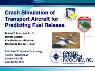
Crash Simulation of Transport Aircraft for Predicting Fuel Release. Robert T. Bocchieri, Ph.D. Robert MacNeill Claudia Navarro-Northrup Douglas S. Dierdorf, Ph.D. 2010 FAA Worldwide Technology Transfer Conference Atlantic City, NJ April 20-22, 2010. Introduction.

E N D
Crash Simulation of Transport Aircraft for Predicting Fuel Release Robert T. Bocchieri, Ph.D. Robert MacNeill Claudia Navarro-Northrup Douglas S. Dierdorf, Ph.D. 2010 FAA Worldwide Technology Transfer Conference Atlantic City, NJ April 20-22, 2010
Introduction • The theoretical critical area/practical critical area (TCA/PCA)1 method has been used for nearly 40 years to determine Aircraft Rescue and Fire Fighting (ARFF) requirements for transport aircraft. • The validity of the TCA/PCA approach is questionable when applied to new transport aircraft. • Does not accommodate modern designs • use of multiple decks • differences in structural crashworthiness • use of composite materials [1] Hall, G.F., B.R. Partin, J.H. Storm, ”Large Frame Aircraft (LFA) Fire Fighting Validation: TCA/PCA Methodology Evaluation”, Air Force Wright Laboratory Final Report WL-TR-95-3071, January, 1995.
Current PCA/TCA Methodology • Definition of minimum agent quantity calculation variables: • Comparison of the Airbus A380 to the Boeing 747 yields roughly the same agent requirement. • (Airbus A380: L=73m, W=7.15m, Boeing 747: L=70.6m, W=6.15m). • Airbus A380 carries about 50% more fuel and passengers. • The A380 clearly has a greater potential for requiring a significantly greater quantity of total agent in initial response vehicles.
Project Objective and Approach • Objective: Provide an alternative methodology to PCA/TCA method. • Technical Approach: • Perform high-fidelity nonlinear dynamic finite element analysis of survivable plane crashes. • Predict time dependent fuel distribution as an input to fire modeling efforts at AFRL for determining ARFF requirements. • Provide bounds on the quantity of fuel dispersed during various types of aircraft incidents. • Leverage modeling methods developed in WTC aircraft impact analyses.
FE Analysis Code: LS-DYNA • LS-DYNA is a general purpose nonlinear dynamic finite element program. • Explicit code architecture • FE Analysis incorporating • Large strains/displacements • Nonlinear material behavior/failure • Dynamic response • Advanced ALE and SPH capabilities for modeling Fluid-Structure Interaction (FSI). • Ideal for crash, impact, blast and penetration applications. • Livermore Software Technology Corporation (LSTC) commercialized LS-DYNA based on development of the DYNA3D code at Lawrence Livermore National Laboratory by LSTC’s founder, John O. Hallquist. • LS-DYNA is optimized for shared and distributed memory Unix, Linux, and Windows based, platforms.
NIST Federal Building and Fire Safety Investigation of the World Trade Center Disaster • ARA conducted Aircraft Impact Analyses • Impact analyses provided predictions of structural damage and fuel dispersal. • National Institute of Standards and Technology (NIST) conducted Fire and Collapse Analyses • Fire analyses performed using fuel dispersal predicted from impact analysis. • Structural collapse predicted from impact and fire analyses. Aircraft Impact Analysis Fire Analysis Structural Collapse Analysis
Fuel Dispersal and Core Damage WTC 2 WTC 1 AVI AVI Interior Tower Contents Transparent Interior Tower Contents Transparent
Project Plan • Phase 1: Proof of Concept – Validation against full-scale crash tests. • Phases 2 & 3: Evaluate fuel dispersal for other transport aircraft • Potentially Airbus A380 and Boeing 787.
Phase 1 – Proof of ConceptValidation with a Full-Scale Crash Test • The FAA conducted full-scale crash tests of commercial transport aircraft in 1965. • These test programs were designed to simulate typical crash conditions during survivable takeoff and landing accidents and collected considerable data on crash loads, accelerations, and fuel containment. • Dyed water was used in lieu of fuel so that that damage was due solely to the impact events and not a subsequent fire. • The Constellation was made from higher-strength, low-elongation aluminum similar to more modern aircraft. Lockheed Constellation Model 1649 [2] Reed, W.H., S.H. Robertson, L.W.T. Weinberg, L.H. Tyndall, “Full-scale Dynamic Crash Test of a Lockheed Constellation Model 1649 Aircraft”, FAA-ADS-38, October, 1965.
Phase 1 – Proof of ConceptValidation with a Full-Scale Crash Test Plan view of Constellation crash test site • Initial impacts at 112 knots removed the landing gear, resulting in the aircraft to be airborne. • Once airborne, the left wing struck an earthen barrier and the right struck two vertical telephone poles. • The constellation had only integral fuel tanks and no bladder tanks.
Phase 1 – Proof of ConceptValidation with a Full-Scale Crash Test Fuel spillage occurring 2.24 seconds after gear impact • Results from this test will be used to validate and refine the computational models. • A well-controlled full-scale crash test focused on determining fuel dispersal is a better approach than making comparisons with real crash incidents. • Accelerometer data, photographic documentation of the crash event and the rate of fuel dispersal from the simulation will be compared with the documented test results. • Modeling methodologies developed and validated in this phase will be used in subsequent phases to evaluate aircraft of interest. 1. Left outboard tank – water. 5. Left root tank – water. 3. Right tank between engine and nacelles – gel. 4. Right outboard tank – water.
Phase 2 – Evaluate Fuel Dispersal from a Modern Transport Aircraft • Implement the validated modeling methodologies from Phase I for assessing fuel dispersal from a modern transport aircraft (e.g., A380). • The focus will be on determining bounds for the rate of fuel dispersal for common impact-survivable crash scenarios • Focus on: • Fuel tank puncture from uncontained engine failure fragments. • High impact landing (Hard Landing). • Ground collision with another structure. Airbus A380
Example Aircraft Crash Incidents • Review of aircraft accident reports of potentially survivable events indicate that there are generally three types of events (engine fragment, hard landing, ground collision). • Many of these incidents are considered fire-incident milestones.
Phase 2 - Impact-Survivable Crash Scenarios • Developed by recommendation of the Special Aviation Fire and Explosion Reduction (SAFER) Advisory Committee for use in future crashworthiness R&D efforts. [3] A Study of Transport Airplane Crash-Resistant Fuel Systems”, DOT/FAA/AR-01/82, NASA/CR-2002-211437, March 2002.
Analysis of Hard Landings and Impact with Ground Hazards • Various parameters will be considered in developing bounds on fuel dispersal. • aircraft speed • ratio of forward velocity to sink rate • aircraft weight and fuel load • gear configuration • The variations in crash conditions will be limited to impact-survivable events and aircraft operational requirements, using the impact conditions recommended by SAFER Committee.
Phase 1 ProgressCrash Site Model Development Landing Gear Barriers • Model of the crash site completed including earth, pole, landing gear barriers and 6 and 20 degree slopes. • Created model of a typical telephone pole (40 ft. tall, 10 in. diameter) made of Southern Yellow Pine using LS-DYNA wood material model created for FHWA crash and impact applications. • “This material model was developed specifically to predict the dynamic performance of wood components used in roadside safety structures when undergoing a collision by a motor vehicle.” 6 degree slope Pole Barriers Earth Barrier Bogie and Pole Models Used to Validate Wood Material Model used for Pole Barriers4 [4] Manual for LS-DYNA Wood Material Model 143, Publication No. FHWA-HRT-0R-097, Aug. 2007
Phase 1 ProgressL-1649 Crash Test Reconstruction Longitudinal Velocity • Accelerometer data and high-speed film being used to reconstruct response of each aircraft component during crash. • Accelerometers were placed at three locations on each wing and five locations in the fuselage. Accelerometer Locations
Truss-type Ribs Phase 1 ProgressL-1649 Model Development Wing Box Finite Element Model • Modified available electronic surface geometry to be suitable for creating a computational mesh of the aircraft. • Structural model for wing box with integral fuel tanks is largely complete. Exterior Surface Geometry Integrally stiffened skin Fuel Tank Ribs Rear Beam Front Beam
Phase 1 ProgressPreliminary Impact Analyses – Pole Barriers • Inboard wing tank compromised after impact with ground, outboard by pole impact. Outboard Pole Impact Inboard Pole Impact
Conclusion • An alternative to the PCA/TCA methodology for determining ARFF requirements is under development. • Method is based on conducting high-fidelity LS-DYNA crash simulations of impact-survivable aircraft accidents. • Utilizes modeling techniques applied in the WTC Disaster investigation. • Provide bounds on fuel dispersal which will serve as input to fire modeling efforts. • ARFF vehicle and agent requirements can then be defined. • Technical Approach involves validation against full-scale crash tests and evaluation of two aluminum-framed transport aircraft. • Future work will include aircraft with a more significant use of composite materials (e.g. Boeing 787): • Will require additional validation against composite structure crash tests.