Download
1 / 66
660 likes | 679 Views
This topic covers the basics of telecommunications, including data transmission, signals, and channels. Learn about analog and digital data, transmission mediums, channel characteristics, and more.

E N D
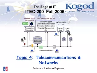
The Edge of ITITEC-200 Fall 2006 Topic 4: Telecommunications & Networks Professor J. Alberto Espinosa
Agenda • Learn the basics about telecommunications • Introduction to networking concepts
Decision SupportDistributed CollaborationEnterprise CollaborationFinancial Managementetc. Information Roadmap BusinessApplications Transaction Processing ServerAppl Client Appl ITInfrastructure DB DB Database IT Infrastrucure: - HW & SW - Database - Telecom IT &Business Business Applications IT & Business
Telecom “Any sufficiently advanced technology isindistinguishable from magic”Arthur C. Clarke (a famous scientist) 2 worlds: Digital signal (what computers understand: e.g., 00111001) Analog signal (what humans sense) 1 0
Data and Transmission Signals • Data is what you want to transmit • Data is transmitted with signals through a communication medium • Data can be analog (sine waves)– i.e., what humans understand (e.g., voice, video) • Or it can be digital (square signals representing 0’s and 1’s)– i.e. what computers understand (e.g., bit and bytes) • Analog and digital data can both be transmitted using eitheranalog or digital signals
Examples of Data and Signals • Computer data over regular phone line dial-up connection (via modem) Digital Data • Internal computer bus • Local area networks • Computer data over digital phone lines (DSL) Original Data Form • Video-conferencing • Digital cable TV • Music CD’s • MP3/media players • Regular telephone (voice transmission) • Regular TV • Analog cable TV • Radio transmission Analog Data Digital Signal Analog Signal Transmission Mode
Digital Signal Digital Signal Analog Signal Computer Computer Modem (Modulation) Modem (Demodulation) Example: How Modems Work Computers send digital signals, but regular telephone lines only transmit analog signals. A modem (modulator/demodulator) converts the digital signals to analog (fast audible beeps) so that the message can be transmitted through telephone lines
Transmission Medium = physical medium through which data signals travel • All signals travel as electromagnetic waves – i.e., pulses (of voltage, light, etc.) at a given frequency (e.g., 1000 pulses per second or 1000 hertz, or 1 kilohertz) – Examples of transmission media: • Twisted wire inexpensive, available in most buildings • Coaxial cable faster, thick, hard to wire • Fiber optic cable expensive, faster, lighter, durable • Wireless slower, flexible (microwave, radio, cellular, infrared)
Transmission Channels • A channel is the link between a sending and receiving point • A medium is usually broken into several channels, depending on the medium’s capacity, so that data can be transmitted simultaneously through various channels:e.g., cable TV signal, cell phone signals
Characteristics of Channels Transmission speed or capacity • How much data you can send per second • Kilo/Mega/Gigabits per second (Kbps/Mps/Gps) • Affected by medium bandwidth, network traffic, noise, transmission errors Transmission Frequency • Cycles per second of the electromagnetic signal • Not necessarily related to transmission speed • It is just the nature of how the signal travels through a medium • Measured in hertz (cycles per second), kilohertz, etc. Bandwidth (see next slide)
Bandwidth • Every data transmission medium (e.g., cables, airwaves, etc.) and each of its channels, have a bandwidth that affect the data transmission capacity of that medium or channel: More bandwidth more channels more capacity to transmit dataMetaphor: wider highway more lanes more traffic capacity • Bandwidth (of a medium or channel) is defined as: the difference between the highest and lowest frequencies that can be transmitted (through that medium or channel) • e.g., if a channel or medium can transmit from 300Mz to 800Mz, the bandwidth is 800 - 300 = 500Mz
Splitting the Medium into Channels • A useful physics principle about electromagnetic waves: waves of different frequencies don’t mix!! (sound check) • Therefore, we can send more than one signal through a medium, provided that each signal uses a different frequency • Ex. You 100+ TV channels through one channel • Ex. Your cell phone signals don’t mix with those of your neighbor • Ex. Signal from radio station doesn’t mix with another station • But if the frequencies of two channels are too close to one another, there may be some interference (noise, etc.)
Bandwidth Animation
Medium and Channel Bandwidth Illustration 800 MHz 700 MHz 600 MHz 500 MHz 400 MHz 300 MHz Channel Bandwidth = 400 MHz – 300 MHz = 100 MHz Medium Bandwidth = 800 MHz – 300 MHz = 500 MHz Number of Channels = 5 = 500 MHz / 100 MHz
Electromagnetic Wave Frequencies Example: WiFi -- 2.4 GHz = 2.4x10⁹ (unregulated frequency) (chart) Kilohertz (KHz) = 103; Megahertz (MHz) = 106; Gigahertz (GHz) =109
Switching • How does data travel over distance from point A to point B? • It travels from the source (the sending point), to the destination (the receiving point) • Going through switching points widely distributed throughout the country (and the world) • Every switching point has equipment (i.e., hardware and software) called “switches” that take care of making the necessary connections and finding the best routes • There are two general types of switching methods:“Circuit Switching” and “Packet Switching”
Circuit Switching San Francisco Washington, DC • Dedicated path (“circuit”) between communication points • Connected through switching nodes • Good for continuous transmissions • e.g., voice and video (e.g., telephone networks) • Inefficient otherwise (idle circuit connection ties up the circuit) Circuit Switches
Packet Switchinge.g. ATM, Frame Relay • Data is broken into packets • Each packet contains destination and re-assembly info (packet #, msg #) • Each packet is sent separately • And reassembled at the receiving end • Good for data transmissions Miami Atlanta Packet Switches
A Network • Is a number (2 or more) of interconnected computer devices • The connecting devices are called “nodes”
Protocols A Protocol = “A set of rules and procedures that govern data transmissions between components in a network” For two entities (e.g., computers, persons, radios) to communicate, there needs to be a protocol • Implemented in software and/or hardware • Examples of protocols: TCP, IP, FTP, HTTP
The Network Layer Architecture • Networks are very complex • Because there are too many HW and SW components communicating with each other • So, ensuring reliable/fast data communications requires numerous networking steps and functions • No single networking component can do this alone • Thus, different networking functions are carried out by different specialized components • These components are arranged in layers. • Each layer function is performed by specific HW and/or SW • Each layer needs to follow the standard communication protocols agreed upon for that layer
Physical Analogy: Postal Service Actual Communication Application: write a letter Application: read the letter Mail Person Mail Person Local Post Office(for zip code) Local Post Office(for zip code) Mail Sorting Facility Mail Sorting Facility Trucks, Airplanes,Trains, etc. Trucks, Airplanes,Trains, etc. Physical Infrastructure: Highways, Sky, Railways, etc. Data Flow
ActualCommunication Another Analogy: A Telephone Network Application:make a phone call Application:receive a phone call Telephone Telephone End Office or PBX End Office or PBX Circuit Switch Circuit Switch Telephone Network Telephone Network Physical Media Physical Media Cables, Airwaves, etc. Data Flow
A Generic 5-Layer Networking Model(each layer has its own set of protocols) Data Communication Applications:E-Mail, Web, Chat, etc. Applications: E-Mail, Web, Chat, etc. Each layer is HW and/or SW performing a distinct function Application Layer Application Layer Transport Layer Transport Layer Network Layer Network Layer Data Link Layer Data Link Layer The data flows from layer to layer and through the network 00100010010 Physical Layer Physical Layer Network Data Flow
Network Layer Architecture: An ExampleFYI Only – no need to study this Application Layer • (SW) Communicates with the softwareapplications (e.g., e-mail, web pages) and break data into small packets and passes the packets to the Transport Layer (and reassembles incoming packets into original data) Transport Layer • (Usually SW) Communicates with the Application Layer, adds some digits for error checking and flow control to each packet, and passes these larger data packets to the Network Layer (and the other way around) Network Layer • (HW and/or SW) Communicates with the Transport Layer, gets each packet, adds network address information necessary to route the packets through the network, and passes these packets to the Data Link Layer (and picks up packets routed from other layers). Data Link Layer • (Usually HW) Communicates with the Network Layer and manage the traffic flow of data packets from the computer to Physical Layer (and acknowledges receipt of incoming packets from other networks). Physical Layer • (HW) Communicates with the Data Link Layer, gets the packets and converts them into (analog or digital) signals that can be transmitted over that particular network physical medium (cable, fiber optics, airwaves) (and converts incoming signals into data packets)
Networking Network = • A facility that interconnects a number of devices • To transmit data from one attached device to another Networks are classified by their GEOGRAPHIC SCOPE: 1. Local Area Networks (LANs) • typically within a single building (e.g. Kogod) or small area (AU) • Metropolitan Area Networks (MANs) are like LANs but for multiple buildings throughout a city. 2. Wide Area Networks (WANs) • over larger geographical areas (e.g., across states, countries) 3. Inter-Networks = “internets” = networks of networks • INTERconnectedNETworks
1. Local Area Networks (LANs) • Small scope network • Typically within a single building (e.g. Kogod) • Or within a small group of nearby buildings (e.g., AU Campus) • If the network spans several buildings throughout a city it is often called a Metropolitan Area Network (MAN) • High data rates
Key Implementation Decisions for LANs Physical Layout • Physical configuration of network cables (i.e., the medium) in buildings • Structured Cabling: • A standard for wiring commercial buildings • Horizontal wires connected vertically via “telecom closets” • Telecom closets connected vertically to closets in other floors • Via a “backbone” cable • Entry point into the building is through the “equipment room” Transmission Medium (physical layer) • Medium used to connect hardware nodes • Twisted pair, co-axial, fiber optics, wireless, etc. Network Topology • Configuration of hardware nodes in the network • Bus (i.e. linear) topology – most predominant today
Bus (linear) Topology w/Hubs • Very popular network is easily scalable via hubs: • Passive Hubs to connect nodes to the network • Active Hubs to connect other hubs (to amplify signal) • Physically, it looks like star topology, but it is “bus topology” • Every hub “extends” the bus • Predominant with “Ethernet” networks (AU’s Novell LAN) Wireless Transceiver Passive Hub Active Hub Terminator Terminator PassiveHub
Wide Area Networks (WANs) • Cover large geographical areas (e.g., across states, countries) • Wired, wireless or both • A company’s WAN is generally implemented by interconnecting all the LANs in the company’s multiple office locations • Each location’s LAN has a ROUTER that connects the LAN to a WAN service provider’s access point • The connection from the router to the WAN service access is called point-to-point connection
Point to Point Connections in WANsNeeded to connect your home or office to a network service provider • DSL:digital subscriber line, fast dedicated(ADSL is asymmetric DSL same as DSL but receive speed is higher than send speed) • ISDN:dial updigital telephone lines, fast • T1, T3, etc.: fastest (1.5 Mbps +), dedicateddigital lines, which is always connected (no need to dialup) • Note: two or more LAN’s in a city can also be interconnected with point-to-point connections (forming a MAN). For example, you can connect two office LANs using a T1 line – the cost depends on the distance between the two offices
Connection Through Network Services in WANsthrough “Packet Switching” Nodes • There are many types of wide area network services, which vary according to the type of packet switching technology they use. The main kinds of switching technologies are: • Frame Relay: • Variable transfer speed • You pay more for faster speeds • Speeds: 64 Kilobytes per second (Kbps) to 45 Mbps • Asynchronous Transfer Mode (ATM) • NOT THE SAME AS A BANK’S ATM • Really fast networks • Very fast data packet switching at fixed speeds • Speed: up to 1 Gbps
Wide Area NetworksGeneral Configuration Frame Relay Network Service LAN 2e.g.New York LAN 1e.g. Dallas T1, T3, or ISDN(point to point) WAN Service access points Server Server ATMNetwork Service ATM Router Frame RelayRouter T1, T3or ISDN(point to point) Client Client
Introduction to Inter-Networks: The Internet, Intranets and Extranets
3. Inter-Networking An “internet” (in lower case) = • a network of networks (i.e., INTERconnected NETworks) • Connected through routers and packet switching nodes (Frame Relay, ATM, etc.) “The Internet” (capitalized) • the most popular public “internet” • All nodes connected to “The Internet” communicated using the same widely adopted & supported protocol = “TCP/IP”
Examples • HTTP (Web) • SHTTP (secure Web) • SMTP, IMAP (e-mail) • FTP (file transfers) • SNMP (network mgt) Ex:EMail, Browsers, etc. “Transmission Control Protocol” Provides a reliable connection between the 2 applications “Internet Protocol”Routing functions across multiple networks using an IP address Ex:Mail Server, Web Server, etc. The TCP/IP Reference Model (Internet = INTERconnected NETworks) Application 1 Related Application Application Layer Application Layer TCP TCP IP IP Network Access Layer Network Access Layer Physical Layer Physical Layer The Internet
Router IP Net 1 Access (protocol 1) Net 1 Access (protocol 2) Physical Layer Network 1 Physical LayerNetwork 2 “The Internet” is a network of networks. A router connects two networks (similar or dissimilar) – e.g., your company’s LAN and its Internet service provider’s network. It routes IP packets from one network to another through it’s IP layer Routers: Application Layer Application Layer TCP TCP IP IP Network Access Layer (protocol 1) Network Access Layer (protocol 2) Physical Layer 1 Physical Layer 2 Network 1 Network 2
Intranets and Extranets An “Intranet” • A company’s internal network • Spanning multiple geographic locations • Interconnected via the Internet instead of a WAN • Usually protected by “Firewalls” • Usually secured with “Virtual Private Networks (VPNs)” An “Extranet” • Similar to an intranet, but external with other companies
Firewalls and VPNs Firewalls • Hardware and/or software that restrict access into and out of a the company‘s internal networks or intranets • They protect your internal network from outsiders • They don’t protect your communications outside “Virtual private networks (VPNs)” • Provide secure internal networks or intranets • Protect your internal communications on the outside • Uses “Tunneling” (encrypt transmissions betw points)
Intranets, Extranets,Firewalls & VPNs (cont’d.) T1, T3, or ISDN(point to point) Internet ServiceAccess Points IPRouter Firewall VPN LAN Company A VPN (Tunnelling) LAN Company B Internet Firewall IPRouter T1, T3or ISDN(point to point) IPRouter VPN Extranet Intranet Firewall LAN Company A
Network Configuration Example: (1) thru the Internet (no WAN) T1, T3, ISDN(point to point) Internet ServiceAccess Points IP Router w/Firewall and VPN LAN Company A LAN Company B IP Router w/Firewall and VPN Internet T1, T3ISDN(point to point) Most commercial routers have built in firewall and VPN functions IP Router w/Firewall and VPN Intranet Extranet LAN Company A
Network Configuration Example: (2) thru WAN + Internet T1, T3, or ISDN WAN ServiceAccess Points IP Router w/Firewall and VPN LAN 1 Company A LAN Company B ATM, Frame Relay or other Router WAN Internet ServiceAccess Points Router w/IP, ATM, Frame Relay, Firewall and VPN support Internet T1, T3ISDN WAN Extranet LAN 2 Company A
Client-Server Architecture • A key technological development in the 90’s • A form of “distributed computing” • Most predominant computing architecture today • Software application (i.e., processing) is split into tasks • These tasks are distributed among computers • Depending where it is more efficient to do the processing
Clients and Servers Clients • Request specialized services from servers, and • Perform other tasks for users (e.g., screen displays) Servers • Acknowledge service requests from clients, and • Provide requested services (i.e., tasks, processes) • Via responses to clients • Servers and clients connect via networks • Client and servers don’t work in isolation, but they are designed to work together (i.e. there is no client without a server, there is no server without a client)
Service Request Response Client-Server Computing(cont’d.) Client Client Server Network Client Server Client Server
Examples of Servers • A server can be hardware, software or both • File Server central file storage, process file requests(ex. Novell’s NetWare, Windows NT) • Database Server back-end DBMS functions (ex. MS SQL Server, Oracle Server, Lotus Notes Server) • Web Server store and fetch web files on request(ex. Apache, Microsoft IIS) • Print Server print job queuing for central printers • Mail Server routes mail to users and other mail servers
Examples of Clients • A client can be hardware, software or both • Networked PCs request files and other services from file servers (Windows 2000, XP) • Database Clients request records from database server, process data locally, screen formatting, etc. (Lotus Notes client, MS Access) • Web Browsers request web files from web servers, translate HTML code into formatted screen displays(Internet Explorer, Netscape) • Mail Client Send/retrieve mail to/from mail servers, organize and display user mail(Outlook Express; Lotus Notes mail client)
Generic Client-Server ArchitectureThere are many variants of this architecture as presented in the next few slides Client Server To format and display information to end users Presentation Software Request Client ApplicationSoftware Server ApplicationSoftware Response Client Communication Software Server Communication Software Client Operating System Server Operating System Client Hardware Server Hardware Network