Download
1 / 46
460 likes | 476 Views
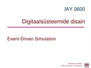
Alexander Sudnitson Tallinn University of Technology. IAY 06 0 0 Digi tal Systems Design. VHDL discussion - 5 - Brief History of VHDL. Data Types. Brief History of VHDL.

E N D
Alexander Sudnitson Tallinn University of Technology IAY 0600Digital Systems Design VHDL discussion -5- Brief History of VHDL. Data Types
Brief History of VHDL VHDL is an industry standardhardware description language that is widely used for specifying, modeling, designing, an simulating digital systems. VHDL is an acronym for VHSIC (Very High Speed Integrated Circuit) Hardware Description Language. The first version of VHDL: IEEE-1076 1987 The most commonly supported by CAD tools version of VHDL: IEEE-1076 1993
VHDL for Synthesis (vs. for Simulation) VHDL was originally developed as a language for describing digital systems for the purpose of documentation and simulation, but not for synthesis. In 1999, the IEEE issued IEEE Std 1076.6-1999, IEEE Standard for VHDL Register Transfer Level (RTL) Synthesis. This standard described a subset of IEEE Std 1076 suitable for RTL synthesis. It also described the syntax and semantics of this subset with regard to synthesis. IEEE 1076.6 defines a subset of the language that is considered the official synthesis subset. A revision of this standard was issued in 2004 and 2008.
VHDL vs. Verilog Features of VHDL and Verilog: • technology/vendor independent • portable • reusable
VHDL for specification, simulation, and synthesis VHDL for Specification VHDL for Simulation VHDL for Synthesis
Predefined scalar types Predifined (built-in) types are those defined in packges STANDARD and TEXTIO in the library STD. Predefined types
Composite type • Array (groups elements of the same type together as single object). A one-demensional array is also called a vector.) • Record (may be of different type)
Fundamental parts of aLibrary Library is a collection of commonly used pieces ofcode, grouped for reuse. LIBRARY PACKAGE 1 PACKAGE 2 TYPES CONSTANTS FUNCTIONS PROCEDURES COMPONENTS TYPES CONSTANTS FUNCTIONS PROCEDURES COMPONENTS
Commonly Used Libraries ieee (Specifies multi-level logic system including STD_LOGIC, and STD_LOGIC_VECTOR data types) std (Specifies pre-defined data types (BIT, BOOLEAN, INTEGER, REAL, SIGNED, UNSIGNED, etc.), arithmetic operations, basic type conversion functions, basic text i/o functions, etc.) work (User-created designs after compilation) Needs to be explicitlydeclared Visible by default
Implicit context clause LIBRARY std, work; USEstd.standard.all;
STD_ULOGIC (enumeration type) Type STD_ULOGIC is declared inpackage STD_LOGIC_1164 as: type_ulogic is ('U‘, ‘X’, ‘0’, ‘1’, ‘Z’, ‘W’, ‘L’, ‘H’, ‘-’);
STD_ULOGIC • Type STD_ULOGIC is unresolved type. By default, types whether predefined or user defined, are unresolved. It is illegal for two sources to drive the same signal (compiler error is generated). • Using STD_ULOGIC has an advantge that if our design unintenentionally creates two sourses for a signal (conflict), we can catch this error during compilation.
Syntax for signal, type, subtype declaration Std_logic is a subtype of std_ulogic subtype std_logic is resolved std_ulogic; resolved is the name of a resolution function
resolved function uninitialized unknown forcing low forcing high high impedance weak unknown weak low weak high Don’t Care Resolution table for std_logic
STD_LOGIC versus STD_ULOGIC • STD_LOGIC is a type declared with a resolution function (defines, for all possible combinations of one or more sorce values, the resulting (resolved) value of a signal). • Example: a circuit with three-state outputs used in a bus interface; this is a situation where we intend for a signal to have multiple sources. Std_logic is a subtype of Std_ulogic (but both consist of the same nine values) and is declared in package STD_LOGIC_1164 (there is defined resolution function with the name resolved.
STD_LOGIC versus STD_ULOGIC A disadvantage of using std_logic instead of std_ulogic is that signals that are unintententionally multiply driven will not be detected as an error during compilation. However, Standard IEEE Std 1164 recomends that std_logic be used instead of std_ulogic, even if a signal has only a single sourse (vendors have to optimize the simulation of models using unresolved types in accordance with Standard).
Three state buffers A three-state buffer is represented by a triangle symbol. Some three-state buffers are enabled when their enable input is '0‘ and others when it is '1'. A three-state buffer has a data input and an enable input. Its enable input controls whether the three-state buffer is OFF and its output is high impedance ('Z'), or whether it is ON and its output is driven by its data input. Thus, the output of a three-state buffer can be either '0', '1', or 'Z'.
Three state buffer description library ieee; use ieee.std_logic_1164.all; entity three_state_buffer is port ( d_in, en_bar : in std_logic; d_out: out std_logic ); end three_state_buffer; architecture dataflow of three_state_buffer is begin d_out <= d_inwhen en_bar = '0' else 'Z'; end dataflow; --If the enable input en_bar is asserted, the buffer’s --output is the same as its input. If the enable input --is not asserted, the buffer’s output is 'Z'.
Multiplexing two data sources If none of the buffers is enabled, both outputs are in their high impedance states and the shared signal they drive has the high impedance value.
Two buffers with their outputs connected library ieee; use ieee.std_logic_1164.all; library three_state_buffer; -- library containing buffer use three_state_buffer.all; entity three_state_bus is port ( d_a: in std_logic;-- data input buffer a en_a_bar: in std_logic; -- enable input buffer a d_b: in std_logic;-- data input buffer b en_b_bar: in std_logic; -- enable input buffer b d_bus: out std_logic -- bused data output ); end three_state_bus;
Two buffers with their outputs connected architecture three_state_bus of three_state_bus is begin u1: entity three_state_buffer port map (d_a, en_a_bar, d_bus); u2: entity three_state_buffer port map (d_b, en_b_bar, d_bus); end three_state_bus; The description assumes that the three-state buffer entity has been compiled to the library three_state_buffer.
Timing waveform For the second input combination, indicated by the cursor, the output for this case is 'X', because one buffer is trying to drive the output to a '1' and the other is trying to drive it to a '0'. On the output waveform, the times during which the output is forcing an unknown value ('X') are represented by two lines. For input conditions corresponding to one buffer enabled and the other not enabled, the output is the same as the enabled buffer’s input value. When both buffers are not enabled, the output is 'Z'. This value is represented on the waveform by a line halfway between the '0' and '1' logic levels.
SIGNAL a : STD_LOGIC; a 1 wire SIGNAL b : STD_LOGIC_VECTOR(7 downto 0); b bus 8 Single Wire versus Bus
STD_LOGIC_VECTOR type type std_logic_vector is array (natural range <>) of std_logic;
Standard Logic Vectors SIGNAL a: STD_LOGIC; SIGNALb: STD_LOGIC_VECTOR(3 DOWNTO 0); SIGNALc: STD_LOGIC_VECTOR(3 DOWNTO 0); SIGNALd: STD_LOGIC_VECTOR(7 DOWNTO 0); SIGNALe: STD_LOGIC_VECTOR(15 DOWNTO 0); SIGNALf: STD_LOGIC_VECTOR(8 DOWNTO 0); ………. a <= '1'; b <= "0000"; -- Binary base assumed by default c <= B"0000"; -- Binary base explicitly specified d <= "0110_0111"; -- You can use '_' to increase readability e <= X"AF67"; -- Hexadecimal base f <= O"723"; -- Octal base
Vectors and Concatenation SIGNALa: STD_LOGIC_VECTOR(3 DOWNTO 0); SIGNALb: STD_LOGIC_VECTOR(3 DOWNTO 0); SIGNALc, d, e: STD_LOGIC_VECTOR(7 DOWNTO 0); a <= "0000"; b <= "1111"; c <= a & b; - -c = "00001111" d <= '0' & "0001111"; -- d <= "00001111" e <= '0' & '0' & '0' & '0' & '1' & '1' & '1' & '1'; -- e <= "00001111"
Single versus Double quote Use single quote to hold a single bit signal a <= '0', a <='Z‘ Use double quote to hold a multi-bit signal b <= "00", b <= "11"
Our use of Std_logic values We are interested in writing descriptions that will be synthesized and then implemented using FPGA (PLD). In PLD/VHDL design methodology we will assign only the values ‘0’, ‘1’, or ‘–’ to std_logic signals. Sometimes we add ‘z’ to the previous list of values. Assigning values ‘H’ and ‘L’ to signals is not compatible with the device technology normally used in FPGAs (PLDs). For testbenches we typically assign only the values ‘0’ and ‘1’ as inputs to the UUT. During simulation we may observe the value ‘U’ and sometimes the value ‘X’. Since we will not assign values ‘H’ and ‘L’ to signals, we don’t expect to obseve the value ‘W’.
The predefined type boolean The predefined type boolean is defined as type boolean is (false, true); This type is used to represent condition values, which can control execution of a behavioral model. There are a number of operators that we can apply to values of different types to yield Boolean values, namely, the relational and logical operators. The relational operators equality (“=”) and inequality (“/=”) can be applied to operands of any type, provided both are of the same type. For example, the expressions 123 = 123, 'A' = 'A', 7 ns = 7 ns all yield the value true, and the expressions 123 = 456, 'A' = 'z', 7 ns = 2 us yield the value false.
The predefined type boolean To make an assignment of the value of one type to one of the others, the type of the value being assigned must be converted to the target type. For example, if signal x is declared as type std_logic_vector and signal y is declared as type unsigned, and they are of equal length, each of the following assignments is illegal: x <= y ; --illegal assignment, type conflict y <= x ; --illegal assignment, type conflict However, appropriate type conversions allow the following assignments to be made: x <= std_logic_vector (y) ; -- valid assignment y <= unsigned (x) ; -- valid assignment
Types UNSIGNED and SIGNED Type std_logic is not defined as a numeric representation, no arithmetic operators are not defined for it in package STD_LOGIC_1164. To avoid confusion separate types were created for numeric representation in package NUMERIC_STD: type unsigned is array (natural range < >) of std_logic; type signed is array (natural range <>) of std_logic; Type signed is interpreted as a signed binary number in 2´s complement form. The leftmost element is the sign bit.
Context clause to use unsigned and signed The type unsigned is defined in pakcage NUMERIC_STD. LIBRARY ieee; USEieee.std_logic_1164.all; USEieee.numeric_std.all;
Type conversion To make an assignment of the value of one type to one of the others, the type of the value being assigned must be converted to the target type. For example, if signal x is declared as type std_logic_vector and signal y is declared as type unsigned, and they are of equal length, each of the following assignments is illegal: x <= y ; --illegal assignment, type conflict y <= x ; --illegal assignment, type conflict However, appropriate type conversions allow the following assignments to be made: x <= std_logic_vector (y) ; -- valid assignment y <= unsigned (x) ; -- valid assignment
Conversion between Std_logic_vector, Unsigned and Signed This conversion is easy to accomplish because these are considered clsely related. Type conversion between closely related types is accomplished by simply using the name of target type as it were a function. For example, if x is std_logic_vector and y is unsigned, and they are ofequal length, than asigments x <= y; and y <= x; are illegal. Type conversions are allowed assignments to be made: x <= std_logic_vector (y); y <= unsigned (x);
Using function to_unsigned This function has two parameters. The first parameter is the integer to be converted. The second is the length of the returned unsigned vector. This vector’s element values are the binary equivalent of the integer value passed to the function. In the statement (a_tb, b_tb) <= to_unsigned (i, n) ; the unsignet vector value returned by the to_unsigned function is assigned to an aggregare made up of the scalar input signals. Since each of these scalar inputs is type std_logic, the assignment is valid.
Functions to convert between types signed and signed and integer Examples: y <= to_unsigned (i, 8); x <= std_logic_vector (to_unsigned (i, 8));
Simplified syntax of package declaration Package is a primary design unit used to organize and collect together related commonly used declarations (constants,types, functions, procedures).
Port types for synthesis A synthesizer must translate all types used for signals into types that can represent wires. Typically, a synthesizer converts all types to either std_logic or std_logic_vector.
VHDL operators are listed from higher to lower precedence a = floor_div(a, n) * n + (a mod n) a = (a / n) * n + (a rem n) 9 mod 5 = 4 9 rem 5 = 4 9 mod (-5) = -1 9 rem (-5) = 4 (-9) mod 5 = 1 (-9) rem 5 = -4 (-9) mod (-5) = -4 (-9) rem (-5) = -4
Shift operators Shift operators. Let A = “10010101” A sll 2 = “01010100” --shift left logical, filled with ‘0’ A srl 3 = “00010010” --shift right logical, filled with ‘0’ A sla 3 = “10101111” --shift left arithmetic, filled with right bit A sra 2 = “11100101” --shift right arithmetic, filled with left bit A rol 3 = “10101100” --rotate left by 3 A ror 5 = “10101100” --rotate right by 5